Dynamic correcting device of digital analog converter

A digital-to-analog converter and dynamic correction technology, which is applied in the direction of analog/digital conversion calibration/testing, can solve problems such as poor dynamic characteristics, and achieve the effect of small impact, strong flexibility, and improved dynamic performance

Inactive Publication Date: 2013-09-11
XIDIAN UNIV
View PDF2 Cites 16 Cited by
  • Summary
  • Abstract
  • Description
  • Claims
  • Application Information

AI Technical Summary

Problems solved by technology

[0006] The purpose of the present invention is to overcome the disadvantages of poor dynamic characteristics of the traditional digital-to-analog converter under the constraints of internal factors and the influence of the external environ

Method used


Image

  • Dynamic correcting device of digital analog converter
  • Dynamic correcting device of digital analog converter
  • Dynamic correcting device of digital analog converter

Examples


Embodiment 1

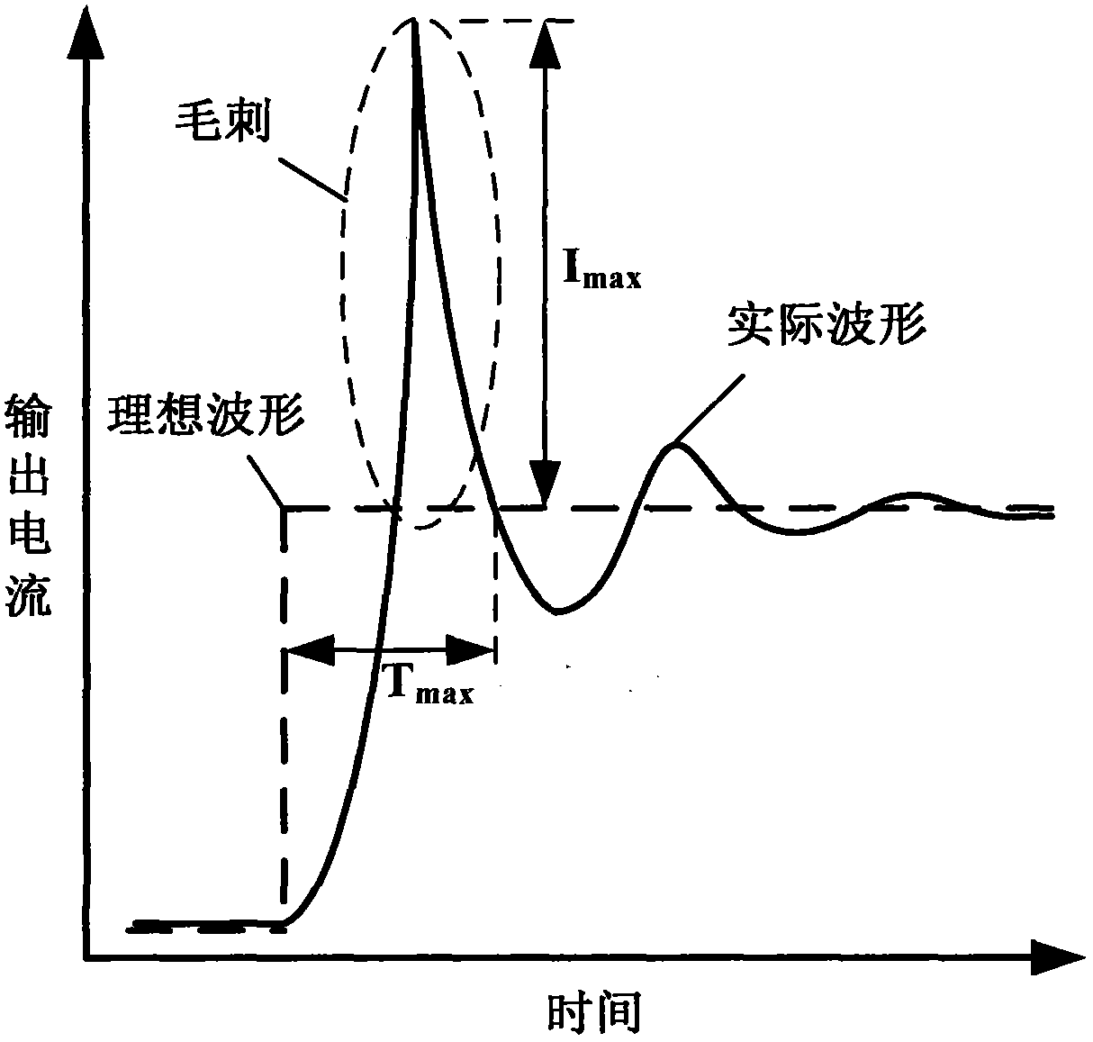
[0041] The current steering type digital-to-analog converter to be corrected in the present embodiment, its number of digits N=12, adopts i+j segmentation structure, i=5, j=7, promptly high 5 are the most significant bits, conversion accuracy I LSB =0.02mA, the uncorrected output current glitch of the digital-to-analog converter is as figure 1 shown, the maximum glitch current I max =0.15mA, the maximum glitch generation time is T max = 0.5ns.

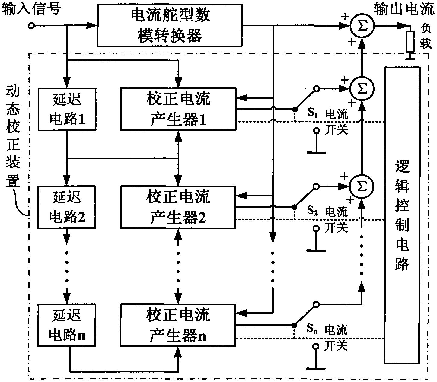
[0042] The present invention is a dynamic correction device for a digital-to-analog converter. The present invention is used to dynamically correct the above-mentioned current steering type digital-to-analog converter. See image 3 The correction device is added between the input and output ends of the current steering digital-to-analog converter, and the correction device includes a delay circuit, a correction current generator, a current switch and a logic control circuit. Wherein, the input and output terminals of the delay circu...

Embodiment 2

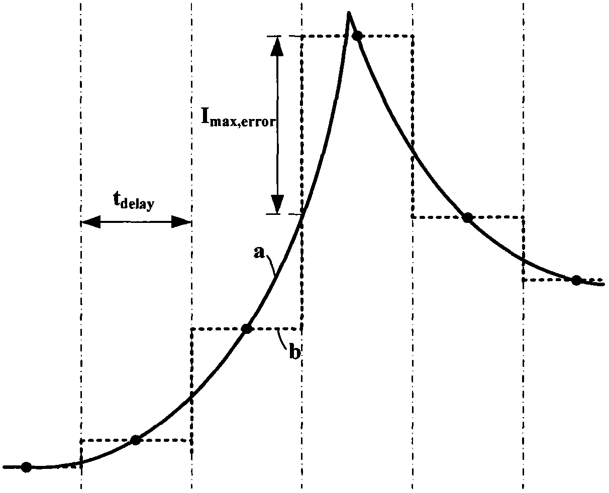
[0054] The present invention is also a dynamic correction method for a digital-to-analog converter, which is executed on the above-mentioned dynamic correction device for a digital-to-analog converter, and the dynamic correction device for a digital-to-analog converter is the same as that in Embodiment 1. The dynamic correction method of the present invention utilizes the principle of current pulse superposition and fitting glitch signal, such as figure 2 shown. Let the curve a in the figure be the glitch current to delay the delay time t of the circuit delay The glitch is divided into several segments for the time step, and the glitch current value at the midpoint of each time segment is used as the fitted current pulse value of each segment; the current pulses of each segment are added in sequence according to the time step to obtain the fitted current curve of the glitch b. The maximum error I between the fitting current and the actual glitch current max,error reflects ...

Embodiment 3

[0068] The structure of the digital-to-analog converter dynamic correction device, the dynamic correction method and various parameters are the same as those in Embodiment 1-2.

[0069] The specific timing situation of dynamic correction in the present invention is as follows Figure 5 As shown, the specific process of combining the sequence diagram is as follows:

[0070] In the correction preparation stage, the logic control circuit grounds all current switches, and the output current is only the output current of the digital-to-analog converter to be corrected; the internal memory of the corrected current generator is in the writing state, and the multi-channel current selector does not work. refer to Figure 4 , correct the sampling clock of auxiliary ADC n in channel n as clk n , the input voltage of the auxiliary ADC n is the output voltage V of the DAC to be corrected out , the row and column input signals of the address decoder n are the input and output signals D o...


PUM


Abstract

The invention provides a dynamic correcting device of a digital analog converter. The dynamic correcting device is added between input and output of a current-steering digital analog converter and comprises delay circuits, correcting current generators, current switches and a logic control circuit. Number of layers of correction channels formed by the delay circuits, the correcting current generators and the current switches can be flexibly set according to correction accuracy. A dynamic correcting method of the digital analog converter includes: in a correction preparation stage, sampling burrs, converting the burrs into correction information and storing the correction information; and in a normal working stage, reading the correction information, and outputting current pulses to compensate burr signals. Multiplex correction current pulses are superposed to correct output current of the digital analog converter successively in a time-phased mode, burrs of the output current are compensated and offset, the technical problem of over-low dynamic performance caused by the burrs is solved, and the internal structure of the digital analog converter is unchanged; the circuit dynamic performance is improved, impact on circuit speed and accuracy is small, and range of use is wide.

Description

technical field [0001] The invention relates to the technical field of mixed-signal integrated circuits, in particular to the dynamic characteristics of a current-steering digital-to-analog converter, and in particular to a dynamic correction device for a digital-to-analog converter. Background technique [0002] Digital-to-analog converters are used to convert digital signals into analog signals, and are widely used in modern communication and signal processing technology fields. In recent years, due to the continuous improvement of the processing speed and precision requirements of the system, the digital-to-analog converter must achieve faster conversion speed and higher conversion accuracy. [0003] The current steering digital-analog converter is the most widely used high-speed and high-precision digital-analog converter at present. It generally includes a decoding circuit, a latch circuit, a current switch and a current source array. The current switch determines the o...

Claims


Application Information

Patent Timeline
IPC IPC(8): H03M1/10
Inventor 庄奕琪汤华莲席望张丽曾志斌
Owner XIDIAN UNIV
Why Eureka
Try Eureka