Non-superimposition beam type fabricated frame-shear wall connection structure and construction method thereof

A technology for connecting structures and shear walls, which is applied to walls, building components, building structures, etc., can solve the problems of large number of steel sleeves, time-consuming, high manufacturing precision requirements, etc., to improve overall performance, convenient construction, and earthquake resistance good performance

Active Publication Date: 2013-09-18
CHINA MCC17 GRP
View PDF8 Cites 24 Cited by
  • Summary
  • Abstract
  • Description
  • Claims
  • Application Information

AI Technical Summary

Problems solved by technology

[0005] In the actual construction of the prefabricated frame-shear wall structure, there are many difficulties in the construction of the connection part of the prefabricated diaphragm wall on the upper and lower floors. Chinese patent document CN102808465A discloses a prefabricated concrete frame-shear wall assembling connection structure and assembling connection method , use the steel bar sleeve to connect the steel bars protruding from the end of the prefabricated part. This connection structure requires high precision in the manufacture of the prefabricated part. In actual construction, due to the heavy weight of the shear wall, it is difficult to move the upper and lower parts in the hoisting state. The layers of reinforcement are aligned one by one, and the number of reinforcement sleeves used in the construction is large, so the operation of aligning and connecting one by one is quite time-consuming

Method used


Image

  • Non-superimposition beam type fabricated frame-shear wall connection structure and construction method thereof
  • Non-superimposition beam type fabricated frame-shear wall connection structure and construction method thereof
  • Non-superimposition beam type fabricated frame-shear wall connection structure and construction method thereof

Examples


Embodiment

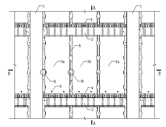
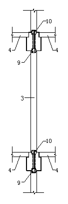
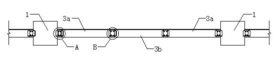
[0037] Embodiment: The non-superposed beam type assembled frame-shear wall connection structure of this embodiment is as follows figure 1 , figure 2 and image 3 As shown, it includes a column 1 prefabricated by concrete, an ear beam 2 and a shear wall 3, the column 1 and the shear wall 3 are connected in sequence in the horizontal direction, and the top of the shear wall 3 is installed with an ear beam 2, Floor slabs 4 are overlapped on the ear beams 2, and post-cast concrete 5 is filled on the connection interfaces of the above-mentioned components.

[0038] Such as Figure 4~6As shown, anchor ring steel bars 8 are pre-embedded on the side wall of the column 1 at the junction of the column 1 and the shear wall 3 . The left and right sides of the shear wall are also equipped with anchor ring steel bars 8. When the shear wall is installed, after the anchor ring steel bars on both sides of the wall are overlapped up and down, vertically insert the vertical connection longit...


PUM


Abstract

The invention relates to a non-superimposition beam type fabricated frame-shear wall connection structure and the construction method thereof. The non-superimposition beam type fabricated frame-shear wall connection structure comprises uprights casted by concrete, shear walls and ear pick beams, wherein the uprights and the shear walls are connected in sequence through column-wall connecting pieces, anchor ring steel bars at the edges of the shear walls as well as vertical longitudinal bars; thick-thin circular steel tubes with different diameters are arranged in the shearing walls vertically, thick-thin circular steel tubes extending out of the top of a shear wall on a lower layer penetrate preformed holes of the ear pick beams placed at the top of the shear wall in an overlapped manner, shuttering is performed at column-wall connecting parts and wall-wall connecting parts, after pouring, concrete pouring is performed, subsequently, prestressed reinforcing steel is used for stretching and drawing a wall body, and grouting is performed after stretching and drawing. The construction method provided by the invention mainly comprises steps of hoisting and mounting the uprights, the shearing walls and the ear pick beams as well as the step of prestress stretching and drawing to upper and lower layers of shearing walls and the like. The invention has the advantages of convenient hoisting and butting, fast mounting speed and the like, can be extensively applied to an assembled monolithic frame-shear wall structure, and has a wide engineering application prospect.

Description

technical field [0001] The invention relates to a prefabricated assembled concrete structure and a construction method thereof, in particular to a non-superimposed beam-type assembled concrete frame-shear wall connection structure and a construction method thereof. Background technique [0002] As a structural form in line with industrial production methods, prefabricated concrete structures have the advantages of fast construction speed, low labor intensity, less noise pollution and wet work, and easy control of product quality. The construction method of prefabricated assembly can effectively save resources and energy, improve the utilization rate of materials in realizing building energy saving and structural performance, overcome the restrictions of construction site and environmental conditions on on-site construction, reduce the number of on-site construction labor, reduce construction waste and Adverse effects of construction on the environment, improving building fun...

Claims


Application Information

Patent Timeline
Patent Type & Authority Applications(China)
IPC IPC(8): E04B2/64E04B1/38E04G21/00
Inventor 潘金龙马军卫尹万云金仁才
Owner CHINA MCC17 GRP
Why Eureka
Try Eureka