
High-speed photoelectric relay

A photoelectric relay, high-speed technology, applied in the field of electronics, can solve the problems of slow discharge speed and slow turn-off speed of relays, and achieve the effect of fast discharge speed

Inactive Publication Date: 2013-09-18
UNIV OF ELECTRONIC SCI & TECH OF CHINA
View PDF4 Cites 3 Cited by
  • Summary
  • Abstract
  • Description
  • Claims
  • Application Information

AI Technical Summary

Problems solved by technology

[0004] Aiming at the technical problem that the current photoelectric relay with a built-in photoelectric control circuit has a slow turn-off speed due to the slow discharge speed, the present invention provides a high-speed photoelectric relay

Method used


Image

  • High-speed photoelectric relay
  • High-speed photoelectric relay
  • High-speed photoelectric relay

Examples


Embodiment Construction

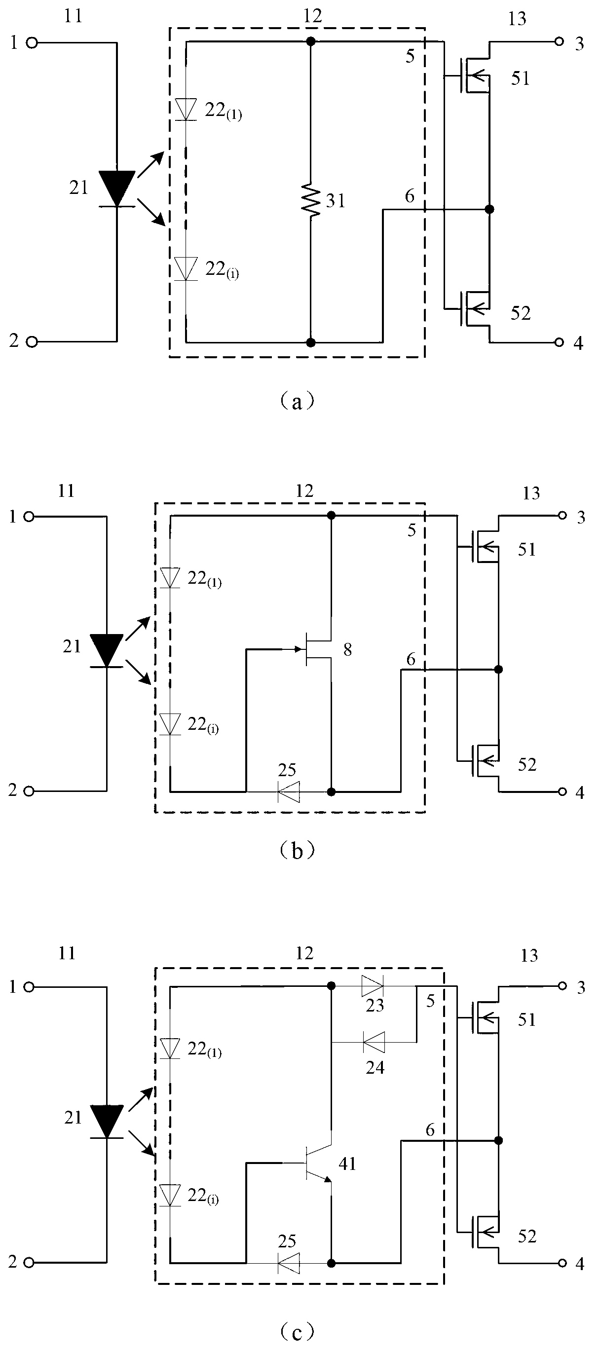
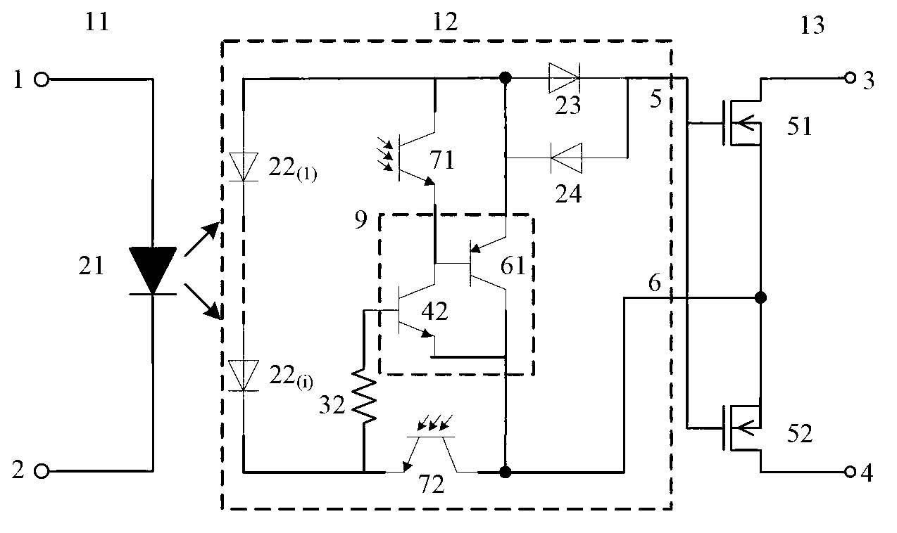
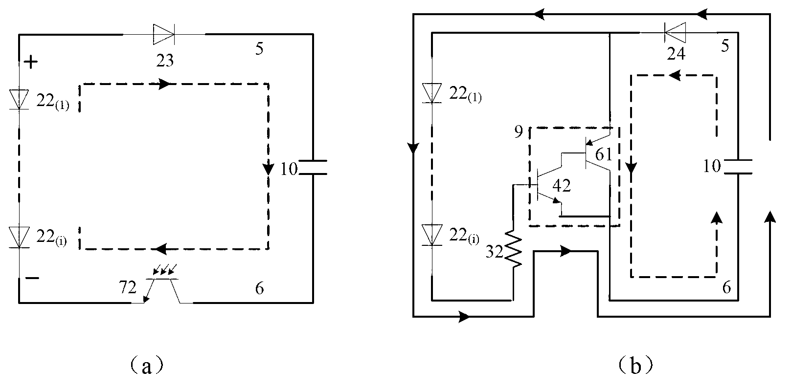
[0028] The invention provides a photoelectric relay, which adopts cascade connection of two-stage or multi-stage triodes as the discharge channel in the control circuit. After the cascade connection, the amplification factor is increased, the discharge capacity of the circuit is enhanced, and the turn-off speed of the power MOSFET is improved.

[0029] figure 1 It is a circuit diagram of a traditional photoelectric relay. The discharge units in the control circuit 12 are (a) a current limiting resistor 31 , (b) a normally-on transistor 8 ; (c) a first NPN transistor 41 . In order to speed up the turn-off time, the gate charge of the output MOSFET should be discharged when turning off, and a fixed current-limiting resistor 31 is used in the control circuit. But when it is turned on, in order to charge the gate of the output MOSFET, the photocurrent from its photovoltaic diode array PDA22 leaks through the current limiting resistor, so the turn-on time will be longer. The disch...


PUM


Abstract

The invention provides a high-speed photoelectric relay, belonging to the technical field of electronics and relating to a photoelectric relay. The high-speed photoelectric relay is improved, aiming at the technical problem of an existing photoelectric relay with a built-in photoelectric control circuit that the photoelectric relay is turned off very slowly due to low velocity of discharge. Two or multiple stages of triodes are connected in cascade to form a Darlington transistor as a discharge channel in a control circuit; after connection in cascade, the amplification factor is increased and the circuit discharge performance is enhanced; after photovoltaic output disappears, the high-speed discharge channel enables the turn-off speed of a power MOSFET (Metal Oxide Semiconductor Field Effect Transistor) to be improved greatly; and therefore, the purpose of rapidly turning off the relay is realized.

Description

technical field [0001] The invention belongs to the field of electronic technology and relates to a photoelectric relay. Background technique [0002] The photoelectric relay is an electronic control device, which uses a photoelectric isolation device to isolate the control terminal from the load terminal. The working principle of the photoelectric relay is to convert the light signal of the light-emitting diode (LED) into an electrical signal through the photodiode array PDA (Photo Diode Array), and control the output stage power MOSFET (Metal Oxide Semiconductor Field Effect Transistor) through the control circuit The turn-on and turn-off of the circuit realizes the driving of the load. The output circuit of the photoelectric relay is usually composed of power MOSFET devices, and the load is driven by turning on and off the MOSFET devices. But in order to reset the relay, the gate electrode of the power MOSFET needs to discharge the charge as soon as possible. [0003] ...

Claims


Application Information

Patent Timeline
IPC IPC(8): H03K17/78H03K17/567
Inventor 乔明李燕妃陈涛许琬蔡林希张波
Owner UNIV OF ELECTRONIC SCI & TECH OF CHINA
Learn More