Furnace-through fixture for reflow soldering

A reflow soldering and furnace passing technology, which is applied in the direction of assembling printed circuits with electrical components, can solve the problems of not obviously increasing the product scrap rate, high cost and manpower, and energy consumption, so as to reduce virtual soldering and open pins The effect of low risk, convenient production and simple structure

Active Publication Date: 2013-09-18
WUXI CHINA RESOURCE MICRO ASSEMBLY TECH
View PDF3 Cites 9 Cited by
  • Summary
  • Abstract
  • Description
  • Claims
  • Application Information

AI Technical Summary

Problems solved by technology

However, such jigs are usually dedicated, and it may be necessary to design a special jig for a circuit board, which requires a lot of cost and manpower to

Method used


Image

  • Furnace-through fixture for reflow soldering
  • Furnace-through fixture for reflow soldering
  • Furnace-through fixture for reflow soldering

Examples


Embodiment Construction

[0025] In order to make the above objects, features and advantages of the present invention more comprehensible, the present invention will be further described in detail below in conjunction with the accompanying drawings and specific embodiments. It should be noted that the structures in the drawings are only schematic rather than limiting, so that those skilled in the art can best understand the principles of the present invention, and they are not necessarily drawn to scale.

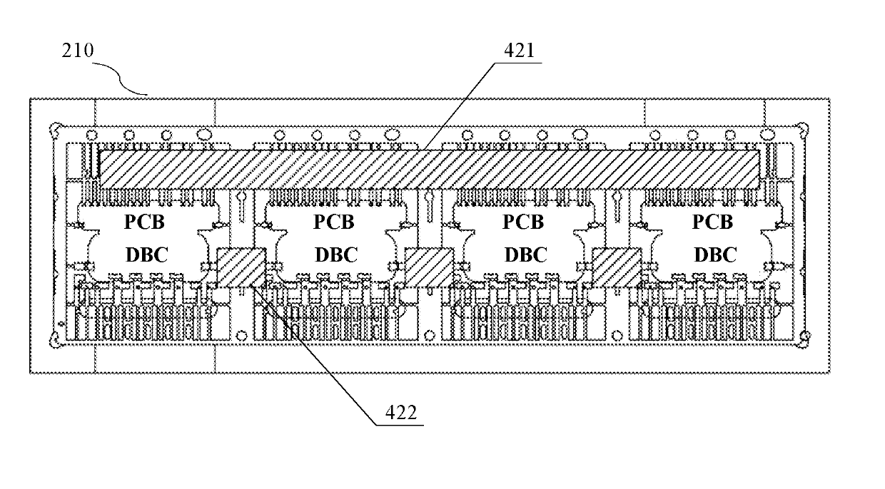
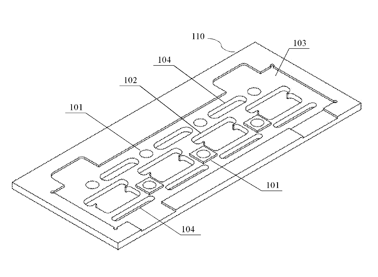
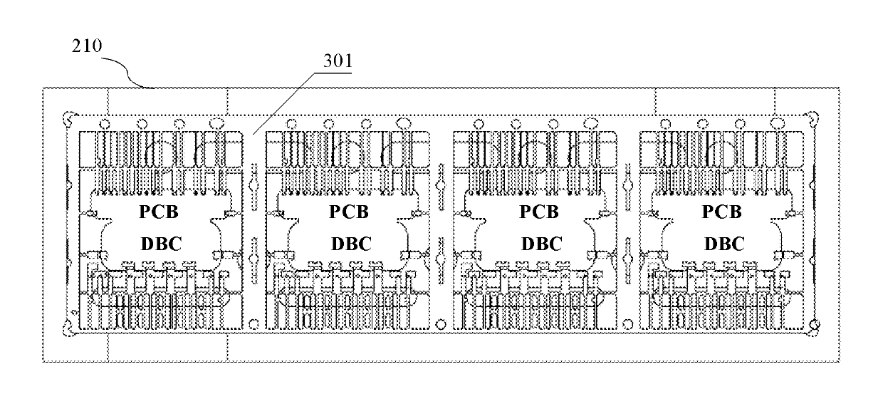
[0026] figure 1 It is a perspective view of a carrier plate of a refractory jig according to an embodiment of the present invention. The reflow fixture provided by the present invention is mainly used to carry the printed circuit board (PCB), copper clad substrate (DBC) and lead frame array required for the manufacture of devices such as intelligent power modules in the reflow soldering process, which mainly includes The carrier plate and the magnetic cover are two parts, in the figure 1 A schemati...


PUM


Abstract

The invention relates to a furnace-through fixture for reflow soldering. The furnace-through fixture is used for bearing printed circuit boards (PCB), direct bounding coppers (DBC) and a lead frame array during the reflow soldering process. The furnace-through fixture comprises: a carrier board which is provided with a plurality of clamp holes for positioning and fixing the PCBs and the DBCs and a clamp groove for positioning and fixing the lead frame array, besides, a plurality of magnetic contacts are arranged on the parts of the carrier board that are beyond the clamp holes and that are covered by the lead frame array; and magnetic covers which are for exerting pressure on the lead frame array that is between the magnetic covers and the carrier board to fasten the lead frame array when the magnetic covers are adsorbed on the magnetic contacts.

Description

technical field [0001] The present invention relates to the manufacture of semiconductor modules, and more particularly relates to a reflow soldering fixture. Background technique [0002] Reflow soldering technology is a commonly used technology in the field of electronic manufacturing. The components on various boards in various electronic devices are soldered to circuit boards by this process. To put it simply, reflow soldering is to provide a heating environment, such as heating air or nitrogen to a high enough temperature and blowing it to the circuit board where the components have been attached, so that the solder paste is heated and melted to make the surface mount components and PCB The pads are reliably bonded together by the solder paste alloy. According to the development of technology, it can be divided into: vapor phase reflow soldering, infrared reflow soldering, far infrared reflow soldering, infrared heating air reflow soldering and full hot air reflow sold...

Claims


Application Information

Patent Timeline
IPC IPC(8): H05K3/34
Inventor 刘晓明张小键王建新龚平王伦波
Owner WUXI CHINA RESOURCE MICRO ASSEMBLY TECH
Why Eureka
Try Eureka