Hollow interlayer heat-insulating wall board and processing and manufacturing method thereof

A thermal insulation wallboard and hollow technology, applied in the direction of thermal insulation, building components, etc., can solve the problems that aluminum foil is not easy to support and tighten, difficult to assemble and process, easy to tear, etc., to meet the cost performance requirements, solve the difficulty of assembly and processing, eliminate The effect of making errors

Active Publication Date: 2013-09-25
河北北方绿野居住环境发展有限公司
12 Cites 1 Cited by

AI-Extracted Technical Summary

Problems solved by technology

[0004] One of the purposes of the present invention is to provide a hollow insulation wallboard to solve the prob...

Method used

D, the making and assembly of elastic inserts: the strip spring sheet is horizontally punched into a right-angled sheet, and then a right-angled side in the right-angled sheet is folded from the middle to the outside to form an acute angle. The angled edge constitutes the elastic card-inserting end of the elastic insert; the end of the other right-angled edge of the right-angled flap is turned into a sharp angle, so that the right-angled edge becomes the pin of the elastic insert. Insert the elastic card-inserting ends of the two structurally symmetrical elastic inserts 3 into the card-insert cavities 7 at both ends of the cross strut 9, so that the prongs on the two elastic inserts 3 are close to the depressed inner concave surface on the end face of the cross strut, In this way, the distance between the convex surface on the elastic insert 3 and the folded edge of the card seat 1 can be minimized.
E, erection of diaphragm roll: choose aluminum foil as the diaphragm of the air interlayer in the insulation wallboard, aluminum foil is wound into diaphragm roll, and the width of diaphragm roll is the distance between two side plates 8 in the housing cavity. Put a diaphragm roller through the core hole of the diaphragm roll, hang the two ends of the diaphragm r...

Abstract

The invention relates to a hollow interlayer heat-insulating wall board and a processing and manufacturing method thereof. The hollow interlayer heat-insulating wall board is characterized in that an air interlayer formed by continuously winding a diaphragm on a support is arranged in a shell, clamping-connection gaps for connecting the support in a clamped manner are reserved at two ends of a side plate of the shell, the support comprises four clamping seats arranged at four corners of the shell and a plurality of transverse supporting rods, the clamping seats are socketed in the clamping-connecting gaps, longitudinally-arranged transverse inserting grooves are formed in long-side plate faces of the clamping seats, elastic inserting pieces are socketed at two ends of each transverse supporting rod respectively, and inserting pins on the elastic inserting pieces are socketed in the transverse inserting grooves in the two clamping seats at the same end and on two sides. The processing and manufacturing method includes separating manufacturing and assembling of the shell from winding and grouping of the diaphragm, independently processing, and thereafter, assembling. The hollow interlayer heat-insulating wall board and the processing and manufacturing method thereof are suitable for being used for manufacturing air heat-insulating wall boards of peripheral guard walls, air heat-insulating load-bearing roof boards used for light roofs, and air heat-insulating hanging boards used for heat insulation outside external walls.

Application Domain

Technology Topic

Image

  • Hollow interlayer heat-insulating wall board and processing and manufacturing method thereof
  • Hollow interlayer heat-insulating wall board and processing and manufacturing method thereof

Examples

  • Experimental program(2)

Example Embodiment

[0029] Example 1: Hollow insulation wallboard.
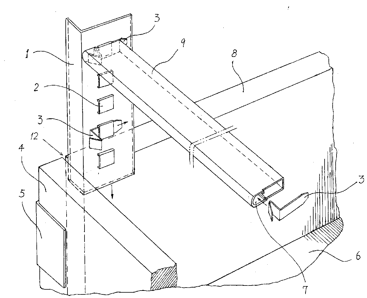
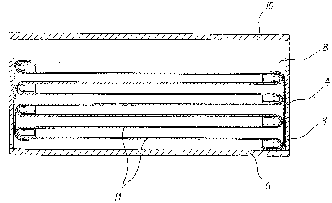
[0030] Such as figure 1 , figure 2 As shown, the hollow interlayer thermal insulation wallboard of the present invention includes two components: a shell and a diaphragm winding.
[0031] The casing is a rectangular parallelepiped shape, which is enclosed by two side plates 8, two end plates 4, a bottom plate 6 and a top plate 10. The two ends of the side plate 8 of the casing and the butt joints with the end plate 4 are respectively pre-set. A clamping gap 12 of about 1 mm is left. The clamping gap can be formed by fixing the end plate and the side plate by the outer fixing plate 5, or by processing the stepped surface of the end surface of the side plate. The top plate 10 on the housing is capped and positioned after the diaphragm winding is assembled.
[0032] The diaphragm winding is continuously bent on the support with the diaphragm 11 to form several air barriers. The diaphragm 11 used is a film material with low emissivity and high reflectivity. Aluminum foil can be selected, or a composite layer with aluminum foil attached to one or both sides of the PET film, or a film coated with aluminum on both sides of the PET film. A kind of film material, preferably 0.9μm thick aluminum foil processing.
[0033] figure 1 In the present invention, the bracket of the present invention includes a clamp 1, a horizontal support rod 9, and elastic inserts 3 that are embedded at both ends of the horizontal support rod 9 to be inserted and matched with the clamp 1. The card holder 1 is a long metal sheet with an L-shaped cross-section, which is separately placed on the inner four corners of the housing (in a buckled state), that is, a flange on the card holder 1 is inserted into the corner of the housing. In the gap 12, the other folded edge of the card holder 1 is pressed against the inner wall of the end of the side plate 8. A number of horizontal slots 2 arranged longitudinally are punched on the folded edge against the inner wall of the side plate, and the horizontal slots 2 are equally spaced. The elastic inserts 3 provided at the two ends of each horizontal support rod 9 are inserted into the horizontal slots 2 on the two holders 1 on the same side end of the shell, so that the horizontal support rod 9 is horizontally connected to the two ends of the shell on the same side. 1 on the deck.
[0034] The horizontal support rod 9 is a hollow flat strip straight rod profile, when it is placed horizontally ( figure 1 As shown), the upper and lower surfaces are parallel planes, and the outer end surface is a convex arc surface. The inner end surface can be a vertical plane perpendicular to the upper and lower surfaces, or a circular arc surface symmetrical to the outer end surface. It can also be other shapes. On the inner walls of the upper and lower sides of the horizontal strut 9 are respectively provided with convex rib-shaped waistlines with opposite upper and lower positions, which are an integral structure with the profile. The upper and lower waistline, the upper and lower planes, and the outer arc surface are combined to form the end surface card cavity 7 of the horizontal support rod 9. The elastic inserting card end of the elastic inserting piece 3 is inserted into the inserting card cavity 7 on the end surface of the cross rod. The arrangement of the two waist lines on the horizontal struts facilitates the positioning of the card insertion end of the elastic insert 3.
[0035] The end surfaces at both ends of the cross support rod 9 are stepped convex and concave surfaces, the end surface of the card insertion cavity is an outer convex surface, and the transverse slot 2 on the card seat 1 is opposite to the inner concave surface on the end surface of the cross support rod 9, so that The end of the cross rod 9 lets out the inwardly convex transverse slot 2 on the card socket 1, so that the edge of the diaphragm 11 supported by the cross rod 9 can be close to the inner wall of the housing side plate 8, so that the diaphragm is not suspended, thereby reducing The occurrence of diaphragm tearing.
[0036] The elastic insert 3 is a right-angled flap ( figure 1 ), then turn one of the right-angled edges of the right-angled flap from its middle to the outside to form an acute-angled edge that forms the elastic card end of the elastic insert; the other right-angle of the right-angled flap The ends of the sides are turned into sharp corners, so that the right-angle sides become the prongs of the elastic insert.
[0037] Insert the elastic card ends of the two elastic inserts 3 with symmetrical structure into the card cavities 7 at the two ends of the horizontal support rod 9 respectively, so that the pins on the two elastic inserts 3 are close to the recessed concave surface on the end surface of the transverse support rod. When the horizontal support rod 9 is inserted into the card socket 1, the pins on the two elastic inserts 3 are inserted into the two horizontal slots 2 of the same height on the two card sockets 1 on the same side of the housing, so that the horizontal The support rod 9 is kept horizontal.
[0038] The diaphragm 11 is continuously bent between the horizontal struts 9 at both ends of the shell to form several air barriers, so that the hollow barrier thermal insulation wallboard forms a good thermal insulation effect.

Example Embodiment

[0039] Embodiment 2: The manufacturing method of the hollow insulation wallboard.
[0040] reference figure 1 , figure 2 , The manufacturing method of the hollow partition insulation wallboard of the present invention includes the following steps:
[0041] a. Production of the shell: On the assembly table, assemble two side plates 8, two end plates 4 and a bottom plate 6 into a cuboid-shaped shell with an open top, and cover the top plate 10 for the top open It is the same size as the bottom plate 6 and is placed for use; when assembling the shell, a 0.9-1.5mm clamping gap 12 is reserved at the two ends of each side plate 8 and the butt joint with the two end plates 4 ( figure 1 ).
[0042] b. The production of the card holder: a long metal sheet is punched along the length into an L-shaped corner card holder 1 ( figure 1 ), a number of equally spaced horizontal slots 2 with horizontal insertion openings are punched longitudinally on one of the folded edges of the card socket 1, and a horizontal slot spacing is reserved between two adjacent horizontal slots 2. Or leave a gap between the thickness of the cross strut. The two card sockets 1 arranged on the two inner corners of each end of the shell are symmetrical. The two rows of horizontal slots 2 on the two card sockets 1 used on each side of the shell correspond to a difference of one horizontal slot (or a horizontal slot). The height of the support rod thickness). The length of the card holder 1 should preferably be consistent with the height of the inner cavity of the housing to avoid misalignment.
[0043] c. The production of horizontal struts: use a profile mold to make a flat straight hollow profile. The cross section of the hollow profile is a quadrilateral. The upper and lower sides are parallel planes, and the outer end surface is a convex arc surface. The inner end face is an elevation perpendicular to the upper and lower planes (reference figure 2 ). The inner walls of the upper and lower planes of the hollow profile are respectively formed with convex rib-shaped waistlines with opposite upper and lower positions. The above-mentioned hollow profile is cut to make horizontal struts 9. After the end surface is polished, the remaining length of each cross strut 9 is slightly smaller than the inner cavity width of the housing minus the thickness of the folded edges of the two holders. File a 1-1.5mm inner concave surface at the end surface outside the card insertion cavity 7 at both ends of each cross bar 9 so that the end surfaces at both ends of the cross bar 9 become stepped convex and concave surfaces; the inner concave surface is used to accommodate Horizontal slot 2 on card socket 1.
[0044] d. Production and assembly of elastic inserts: stamp the strip spring sheet transversely into a right-angled flap, and then turn one of the right-angled edges of the right-angled flap from the middle to the outside to form an acute angled edge. The corner edge constitutes the elastic card end of the elastic insert; the end of the other right angle side of the right angle flap is turned into a sharp corner, so that the right angle side becomes the pin of the elastic insert. Insert the elastic card ends of the two elastic inserts 3 with symmetrical structure into the card cavities 7 at both ends of the horizontal support rod 9 respectively, so that the pins on the two elastic inserts 3 are close to the recessed inner concave surface on the end face of the transverse support rod. In this way, the distance between the convex surface on the elastic insert 3 and the folded edge of the holder 1 can be minimized.
[0045] e. Erection of diaphragm roll: select aluminum foil as the diaphragm of the air barrier in the thermal insulation wallboard, and wind the aluminum foil into a diaphragm roll. The width of the diaphragm roll is the distance between the two side plates 8 in the inner cavity of the shell. A diaphragm roll is threaded into the core hole of the diaphragm roll, and both ends of the diaphragm roll are hung on a laying frame, which is set on the upper track and can reciprocate on the track. Two tape positioning mechanisms can also be set on the laying frame. The tape positioning mechanism is provided with a tape roll. The tape on the tape roll is attached to both sides of the aluminum foil as the aluminum foil on the diaphragm roll is stretched to improve the tear resistance of the aluminum foil. Crack strength.
[0046] f. The production of the operating table: A rectangular frame with adjustable length and extension is set on the frame, and clamping mechanisms for fixing the card holder 1 at the corners of the frame are respectively arranged on the rectangular frame near the four corners. There is also a synchronous pressing mechanism that can press down the four holders together; this constitutes an operating table that can reciprocately wind the diaphragm on the support, and the operating table is located in the diaphragm roll laying frame and rails. Just below the diaphragm roll laying mechanism.
[0047] g. Diaphragm winding production: the four corners of the rectangular frame of the operating table are respectively positioned with a clamp 1 through the clamping mechanism, and the spatial positions of the four clamps 1 on the four corners of the frame are consistent with the installation positions in the housing. Insert the pins of the elastic inserts 3 installed at the two ends of the horizontal support rod 9 horizontally from the outside to the inside of one end of the frame into the lowest horizontal slot 2 of the two card sockets 1 at that end, and then roll the diaphragm After leaving a margin not less than the height of the holder, the end of the drawn diaphragm 11 is glued to the bottom surface of the horizontal support rod 9, and then pulled or driven to the other end of the frame along the track in the diaphragm roll laying mechanism Lay the frame so that the diaphragm 11 on the diaphragm roll is gradually pulled apart on the opposite side of the frame on the top surface of the cross strut 9. After the stretched diaphragm 11 exceeds the two holders 1 at the opposite end of the frame, insert another horizontal support rod 9 horizontally into the lowest transverse slot 2 of the two holders 1 at the opposite end to remove the diaphragm 11 from The horizontal support rod is bypassed downward and upward, and then the laying frame is pulled or driven to the initial end of the frame to make the diaphragm 11 wrap around to the initial end. After the stretched diaphragm 11 exceeds the two holders 1 at the initial end of the frame, the second horizontal support rod 9 at the local end is inserted horizontally into the second lower transverse slot 2 of the two holders 1 at the initial end to make the film 11 oriented The opposite end wraps around. In accordance with the above-mentioned reciprocating cycle of "starting end inserting rod-stretching diaphragm-end inserting rod-stretching diaphragm", the horizontal support rods are inserted layer by layer from bottom to top and the diaphragm is laid back and forth until there is a horizontal support on the top layer. After the rod 9 is inserted, the last layer of diaphragm 11 is glued and fixed to the uppermost horizontal support rod 9 after a certain amount of end margin is reserved. Finally, seal the reserved ends of the diaphragm at both ends to cover the end of the end, and stick the end of the diaphragm 11 to the diaphragm layer at the corresponding position with tape, thereby sealing all the gaps at the end of the cross-strut. All winding work of the diaphragm winding.
[0048] Assembly of thermal insulation wall panels: transfer the auxiliary frame system with diaphragm windings to the top of the assembly table through the hanging rails and align them with the upper mouth of the shell, so that the lower edges of the four clips 1 are aligned with the sides of the side plate 8 of the shell. The end is clamped in the gap 12, and then the four clamps 1 in the diaphragm winding are linearly pushed down from the auxiliary frame into the clamping gap 12 between the side plate 8 and the end plate of the housing by a pressing mechanism. The smooth transposition of the auxiliary frame into the housing completes the installation and positioning of the diaphragm winding in the housing. After the diaphragm winding is installed and positioned, the top plate 10 is sealed on the upper mouth of the shell, all the gaps are sealed and glued, the thermal insulation wallboard is packaged, put into storage, and stored to complete the entire production work of processing and assembly.
[0049] h. Assembly of the thermal insulation wallboard: move the operating table with the diaphragm winding to the top of the assembly table through the slide rail, and align the lower edges of the four holders 1 in the diaphragm winding with the openings on the assembly table. The four corners of the inner side of the housing are clamped in the gaps 12, then the clamping mechanism is released, and the upper edge of the holder 1 is pressed up and down from the frame by the synchronous pressing mechanism to move the diaphragm winding into the housing as a whole, and finally the holder 1 is fully pressed into In the clamping gaps 12 at the four corners of the housing, the positioning of the diaphragm winding in the housing is completed. Finally, the top plate 10 is buckled on the upper mouth of the shell and encapsulated. After all the gaps are sealed and glued, the thermal insulation wall panels are packaged, put into storage, and stored to complete the production work of the entire thermal insulation wall panel processing and assembly.

PUM

no PUM

Description & Claims & Application Information

We can also present the details of the Description, Claims and Application information to help users get a comprehensive understanding of the technical details of the patent, such as background art, summary of invention, brief description of drawings, description of embodiments, and other original content. On the other hand, users can also determine the specific scope of protection of the technology through the list of claims; as well as understand the changes in the life cycle of the technology with the presentation of the patent timeline. Login to view more.

Similar technology patents

Multi-cell metal porous structure

Owner:SHENZHEN CANSINGA TECH CO LTD

Classification and recommendation of technical efficacy words

  • Increased bending stiffness
  • Simple and efficient operation

Ultrathin carbon fibers

InactiveUS20060062715A1Increased bending stiffnessSolving the Insufficiency of ElasticityMaterial nanotechnologyCarbon compoundsAspect ratioRaman spectroscopy
Owner:HODOGAYA KAGAKU IND

Energy-absorbing vehicle hood

InactiveUS7399028B1Increased bending stiffnessLow and uniform crush stiffnessVehicle seatsPedestrian/occupant safety arrangementEnergy absorbingHOOD assembly
Owner:GM GLOBAL TECH OPERATIONS LLC

Method for preparing bi-(sulfonyl fluoride) imine and (fluorinated alkyl sulfonyl fluorine sulfonyl) imine alkali metal salt

ActiveCN101747242AAvoid product agglomerationSimple and efficient operationSulfonic acid amide preparationSolventDecomposition
Owner:武汉市瑞华新能源科技有限公司
Why Eureka
Try Eureka