Cutting torch and manufacturing method thereof

A manufacturing method and cutting nozzle technology, applied in the direction of combustion method, gas fuel burner, combustion type, etc., can solve the problems of inability to clean slag, difficult disassembly and disassembly of cutting nozzles, etc., to improve strength and heat resistance Sexuality and other properties, unobstructed air outlet, and easy coordination

Inactive Publication Date: 2013-09-25
青岛注成金属有限公司
View PDF6 Cites 24 Cited by
  • Summary
  • Abstract
  • Description
  • Claims
  • Application Information

AI Technical Summary

Problems solved by technology

Traditional cutting nozzles are generally produced by mechanical processing, and they have to go through dozens of processes such as turning, drilling, and tapping. The materials are generally brass and copper. dis

Method used


Image

  • Cutting torch and manufacturing method thereof
  • Cutting torch and manufacturing method thereof
  • Cutting torch and manufacturing method thereof

Examples


Embodiment 1

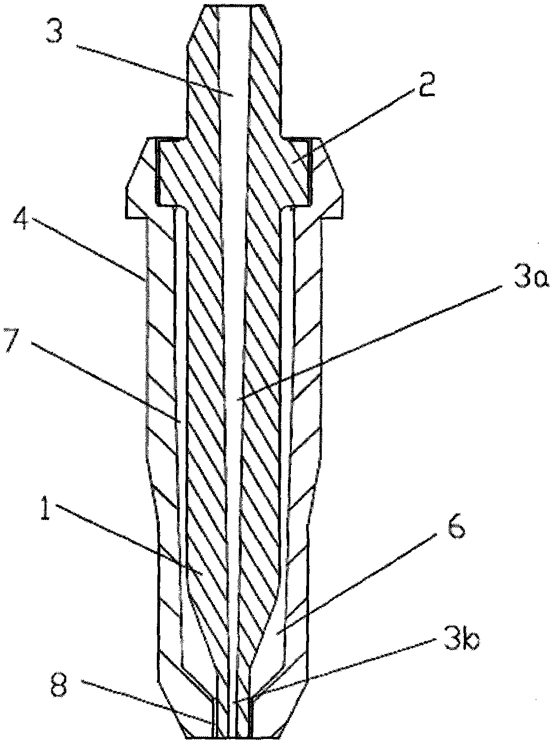
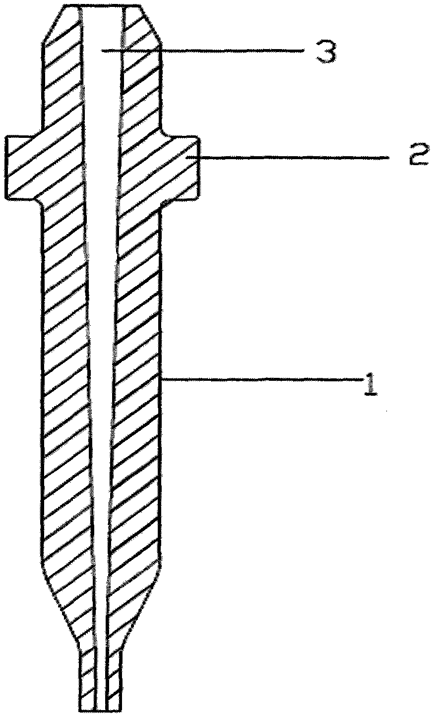
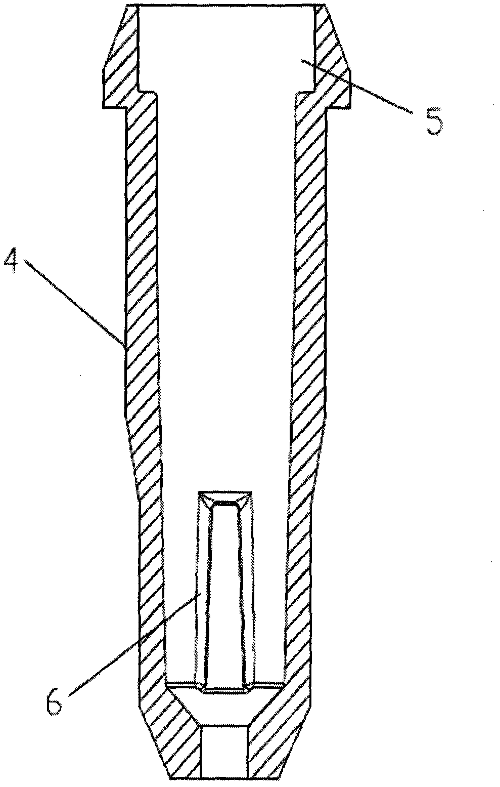
[0029] Example 1 as figure 1 As shown, a cutting nozzle is composed of a central tube 1 and a shell 4; the outer wall of the central tube 1 is provided with a wing platform 2; the inner wall of the shell 4 is provided with a sinker 5 and a rib platform 6; , where the wing platform 2 of the center tube matches the sinking groove 5 on the inner wall of the shell, and axially positions the center tube 1 and the shell 4, and the rib platform 6 on the inner wall of the shell contacts and cooperates with the outer wall of the core tube of the center tube 1, and aligns the center The tube 1 and the shell 4 are radially positioned to ensure the concentricity of the central tube 1 and the shell 4; the central tube 1 is provided with an oxygen channel 3, and the oxygen channel is divided into two sections: a conical section 3a and a cylindrical section 3b; the central tube 1 A gas channel 7 is formed between the outer wall and the inner wall of the shell 4, and the gas channel 7 forms a...

Embodiment 2

[0032] Embodiment 2 A manufacturing method of a cutting nozzle. In this embodiment, the production cutting nozzle is made of 17-4PH stainless steel material, and the central tube 1 and the shell 4 of the cutting nozzle are processed and manufactured by using the powder metallurgy process. The specific steps are as follows:

[0033] (1) Select 17-4PH stainless steel metal powder that meets the specification requirements. The stainless steel powder is produced by water atomization or gas atomization process, with a particle size range of 2-20 μm and a tap density of 45%.

[0034] (2) Select the molding binder suitable for 17-4PH stainless steel powder, carry out mixing and granulation with the stainless steel powder and binder using a high-speed mixer and an extruder, and make feed suitable for injection molding; Percentage by weight, 17-4PH stainless steel powder accounts for 85% of the feed, and the binder accounts for 15% of the feed; the binder is polypropylene, polystyrene, ...


PUM

PropertyMeasurementUnit
Tap densityaaaaaaaaaa

Abstract

The invention relates to a cutting torch of a cutting saw for cutting metal and belongs to the field of flame cutting tool. The cutting torch comprises a central tube and an outer housing; the central tube is inserted into the outer housing for assembling; wing platforms are arranged on the outer wall of the central tube and an oxygen passage is arranged inside the central tube; sinking grooves and rib platforms are arranged on the inner wall of the outer housing; after the central tube is inserted into the outer housing, the wing platforms are matched with the sinking grooves, each rib platform on the inner wall of the outer housing and the central tube are contacted with each other for positioning; the central tube and the outer housing are positioned in the radial direction; after the central tube is inserted into the outer housing, a fuel gas passage is formed between the outer wall of the central tube and the inner wall of the outer housing; a fuel gas nozzle is formed by the fuel gas passage at the head end of the cutting torch, which is close to the rib platforms. The invention provides a manufacturing method for cutting torch, the central tube and the outer housing of the cutting torch adopts a powder metallurgy technology and are formed at one step, so that the fabricating technology is simplified, the production efficiency is improved greatly, the utilization rate of the raw material can reach more than 99%, the texture of material can be replaced flexibly according to different performance requirements of the cutting torch.

Description

technical field [0001] The invention relates to a sawing nozzle for cutting metal and belongs to the field of flame cutting tools. Background technique [0002] Gas flame cutting technology is widely used in various manufacturing industries and metal cutting fields in other industries. The equipment used is a cutting torch, and the cutting nozzle is an important part of the cutting torch, which is very important to the performance of the entire cutting torch. The nozzle is generally composed of three parts: the cutting nozzle core seat, the cutting nozzle core and the cutting nozzle jacket, and the three parts are connected by threads. The typical example is the jet-suction welding and cutting torch that is widely used now. my country formulated and implemented standards related to this product in 1985 (national standard GB5110-85, Ministry of Machinery standard JBT6969-1993). Until now, most manufacturers still The production of cutting nozzle products is based on this stan...

Claims


Application Information

Patent Timeline
IPC IPC(8): F23D14/42B22F3/22
Inventor 李会民徐磊
Owner 青岛注成金属有限公司
Why Eureka
Try Eureka