Eureka AIR delivers breakthrough ideas for toughest innovation challenges, trusted by R&D personnel around the world.

Small two-stage light-gas gun

A light air gun, small technology, applied in the types of weapons, compressed air guns, weapons without explosives, etc., can solve the problems of inability to increase the projectile launching speed, occupy a large space, and cannot be sealed, so as to improve safety and environmental protection, The effect of small footprint and reduced test cost

Active Publication Date: 2013-09-25
HARBIN INST OF TECH
View PDF5 Cites 37 Cited by
  • Summary
  • Abstract
  • Description
  • Claims
  • Application Information

AI Technical Summary

Problems solved by technology

[0005] The purpose of the present invention is to solve the problems that the existing light gas cannon is driven by gunpowder at the first level, pollutes the environment, occupies a large space, and cannot seal the process of high-pressure gas membrane rupture and cannot increase the firing speed of projectiles, and then provides a small two-stage light gas cannon

Method used


Image

  • Small two-stage light-gas gun
  • Small two-stage light-gas gun
  • Small two-stage light-gas gun

Examples


specific Embodiment approach 1

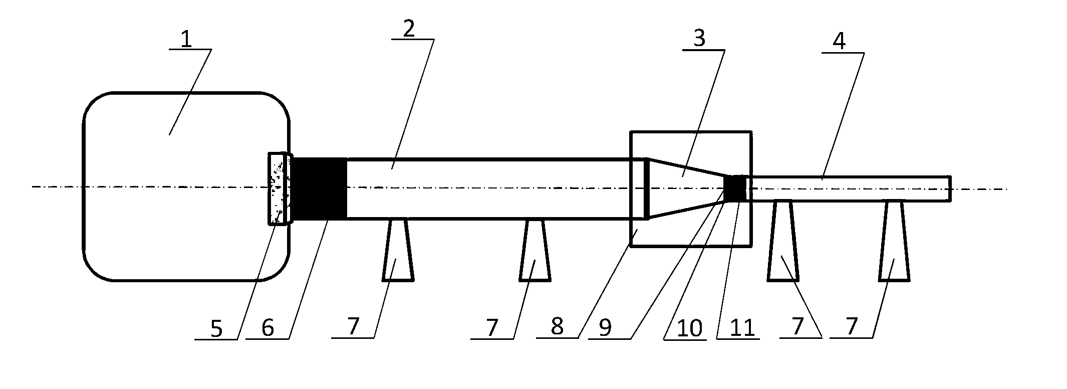
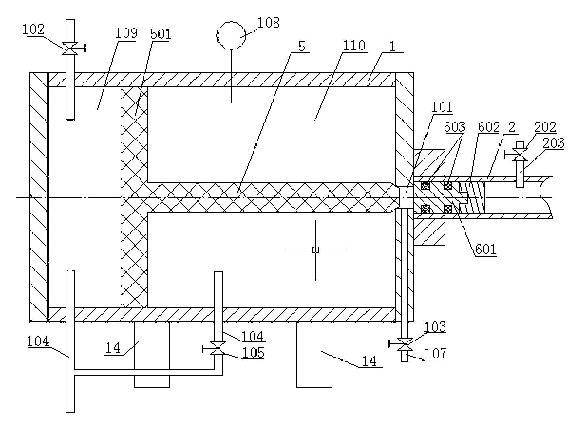
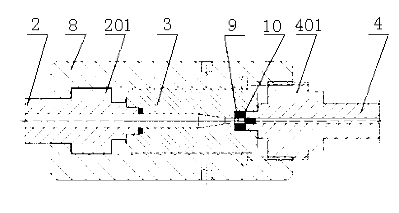
[0014] Specific implementation mode one: combine Figure 1-Figure 6 Describe this embodiment, a small two-stage light gas gun in this embodiment includes a cylinder 1, a pressure guide tube 2, a stamping column 3, a launch tube 4, a piston handle 5, a pressure guide body 6, a diaphragm 9, a ruptured membrane Device 10, first sealing ring 12, metal sealing ring 13, support 14 and a plurality of support seats 7; the cylinder 1 is a cylinder with both ends closed, and the middle part of one end of the cylinder 1 is provided with an air guide hole 101 , the cylinder 1 is equipped with a piston handle 5, the piston 501 on the piston handle 5 is in sliding contact with the inner peripheral surface of the air chamber 1, the end of the piston handle 5 points to the air guide hole 101 and the two are coaxially arranged, the piston 501 connects the cylinder The cylinder 1 is divided into a balance chamber 109 and an air chamber 110;

[0015] A first cylindrical hole 301 is provided in ...

specific Embodiment approach 2

[0022] Specific implementation mode two: combination Figure 1-Figure 6 Describe this embodiment, the outer wall of the metal cylinder 601 of this embodiment and the inner wall of the pressure guiding tube 2 are sealed by the rubber sealing ring set on the metal cylinder 601; The membrane breaker 10 is sealed, the membrane breaker 10 is sealed and connected to the launch tube 4 through the rubber sealing ring installed on the membrane breaker 10, and the pressure guiding tube 2 is sealed and connected to the punching column 3 through the rubber sealing ring installed on the punching column 3 . Such setting ensures a good seal during the process of compressing hydrogen, effectively ensuring the high-speed launch of projectiles under high pressure or ultra-high pressure. This embodiment solves the problem of effective conversion of high-pressure gas driving energy. Or helium, controlled by multiple factors such as piston, stamping column and diaphragm. Due to the limitation of...

specific Embodiment approach 3

[0023] Specific implementation mode three: combination Figure 4 The present embodiment will be described. The cross sections of the first seal ring 12 and the metal seal ring 13 in this embodiment are both circular. Such an arrangement effectively ensures that the pressure guide body compresses the hydrogen until the membrane ruptures without hydrogen leakage. Others are the same as in the first or second embodiment.


PUM

PropertyMeasurementUnit
Thicknessaaaaaaaaaa
Diameteraaaaaaaaaa
Diameteraaaaaaaaaa

Abstract

The invention discloses a small two-stage light-gas gun and relates to a light-gas gun. The small two-stage light-gas gun comprises a cylinder barrel, a pressure transmitting tube, a pressing column, a launching tube, a piston handle, a pressure transmitting body, a membrane, a membrane rupturing device, a first sealing ring, a metal sealing ring, a support and a plurality of supporting seats; a piston on the piston handle is in sliding contact with the inner circumferential surface of a gas chamber; one end of the pressure transmitting tube is connected with a gas port in a threaded manner, and the pressure transmitting tube is hermetically connected with the pressing column; the pressure transmitting body is mounted in the pressure transmitting tube; the first sealing ring and the metal sealing ring are mounted in a mounting groove from the inside to the outside, the membrane is hermetically connected with the membrane rupturing device, and the membrane rupturing device is hermetically connected with the launching tube; the cylinder barrel is mounted on the support, and the pressure transmitting tube and the launching tube are respectively detachably connected onto the supporting seats. The small two-stage light-gas gun has the advantages that problems that an existing light-gas gun is driven by gunpowder at a primary stage, accordingly, environments are polluted, occupied space is large, sealing cannot be carried out in a membrane rupturing procedure implemented by the aid of high-pressure gas and the bullet launching speed cannot be increased are solved, and the small two-stage light-gas gun is used in fields of spacecrafts or research on material performance and the like.

Description

technical field [0001] The invention relates to a light gas gun, in particular to a small light gas gun with two stages of light gas. Background technique [0002] Light gas guns can launch projectiles of different shapes and materials to meet the needs of various high-speed and ultra-high-speed experiments. At present, they are widely used in the research of kinetic energy weapon effects, geospace physics research, spacecraft protection research, and material performance research under high strain rates. It is the most common high-speed and ultra-high-speed drive equipment. [0003] A miniature two-stage light gas gun jointly built by the California Institute of Technology and NASA (NASA), the first-stage gunpowder is driven, the second-stage uses helium or hydrogen, and the diameter of the launch tube is 1.8mm, which can launch 22.7mg steel balls. To 2-3km / s, launch the 3.6mg nylon ball to 5-6km / s. A miniature secondary light gas gun from Tokyo Institute of Technology, J...

Claims


Application Information

Patent Timeline
IPC IPC(8): F41B11/62F41B11/72
Inventor 张伟魏刚任鹏冯恩
Owner HARBIN INST OF TECH
Why Eureka
Eureka Blog
Learn More