
Sine oscillator

A technology of sinusoidal oscillation and main amplifier, applied in the direction of power oscillators, electrical components, etc., can solve the problems of dangerous turn-on and turn-off methods, loose coupling, low sensitivity, etc., achieve reasonable turn-on and turn-off methods, and enhance stability , the effect of high sensitivity

Inactive Publication Date: 2013-09-25
UNIV OF SHANGHAI FOR SCI & TECH
View PDF3 Cites 8 Cited by
  • Summary
  • Abstract
  • Description
  • Claims
  • Application Information

AI Technical Summary

Problems solved by technology

However, because the output voltage and the feedback voltage are coupled by the magnetic circuit, the coupling is not tight, the amplitude of the resonant circuit is required to be large enough, and the loss is large, and due to the limitation of the distribution parameters of the transformer, the oscillation frequency cannot be too high
On the other hand, due to the large size of the transformer, it is not conducive to the small integration of the oscillator
[0006] Other types of sine wave oscillators such as three-point oscillators, crystal oscillators, RC oscillators, etc. overcome the shortcomings of transformer coupling oscillation loss, low sensitivity, low frequency, and large size, but these oscillators do not provide effective and reasonable opening and shutdown mode
At this stage, the turning on and off of the oscillating circuit is realized by supplying power to the oscillating circuit and power off, which is a relatively dangerous way of turning on and off
First, because the oscillating circuit is different from the resistive load circuit, it usually contains multiple capacitors and inductors, which generate more harmonics during the hard turn-on and turn-off process, and these harmonics are harmful to the stability of the peripheral circuit system
Second, after the oscillating circuit stops power supply, it will still oscillate for a period of time, and the voltage swing of the resonant circuit may exceed the system power supply voltage range, causing the peripheral circuit current to flow back, which is another potential hazard to the stability of the circuit system

Method used


Image

  • Sine oscillator
  • Sine oscillator
  • Sine oscillator

Examples


Embodiment Construction

[0026] The sinusoidal oscillator of the present invention will be described in detail below with reference to the accompanying drawings. Those skilled in the art should understand that the embodiments described below are only illustrative illustrations of the present invention, and are not intended to limit it in any way.

[0027] Such as image 3 As shown, the sinusoidal oscillator of the present invention includes an LC parallel resonant circuit 1, an amplifying circuit 2 containing a main amplifier, a positive feedback network 3 containing an operational amplifier, and a control circuit 4 containing a signal control switch. In addition, the shown sinusoidal oscillator also includes a signal output port 5 . Furthermore, the shown sinusoidal oscillator is also connected to a power supply 6 .

[0028] The LC parallel resonant tank 1 is composed of an inductance L1 and a capacitor C4 connected in parallel. The capacitance value C of capacitor C4 and the inductance value of i...


PUM


Abstract

The invention discloses a sine oscillator. The sine oscillator comprises a main amplifier, a LC (Inductor-Capacitor) parallel resonance loop, an operational amplifier and a signal control switch, wherein the main amplifier is provided with a base electrode, a collector electrode and an emitter electrode; the LC parallel resonance loop is formed by connecting an inductor and a capacitor in parallel and connected with the collector electrode of the main amplifier; the operational amplifier is used for providing a positive feedback signal; the operational amplifier is provided with a same-phase input end, an inverted-phase input end and an output end, wherein the output end of the operational amplifier is connected with the base electrode of the main amplifier; the inverted-phase input end of the operational amplifier is connected with the collector electrode of the main amplifier by a first resistor; the inverted-phase input end of the operational amplifier is further connected with the output end of the operational amplifier by a second resistor; and the signal control switch is connected with the same-phase input end of the operational amplifier. The sine oscillator disclosed by the invention is high in sensitivity, small in loss, small in size and convenient to integrate. Besides, the on-off way of the oscillating circuit of the sine oscillator disclosed by the invention is more reasonable.

Description

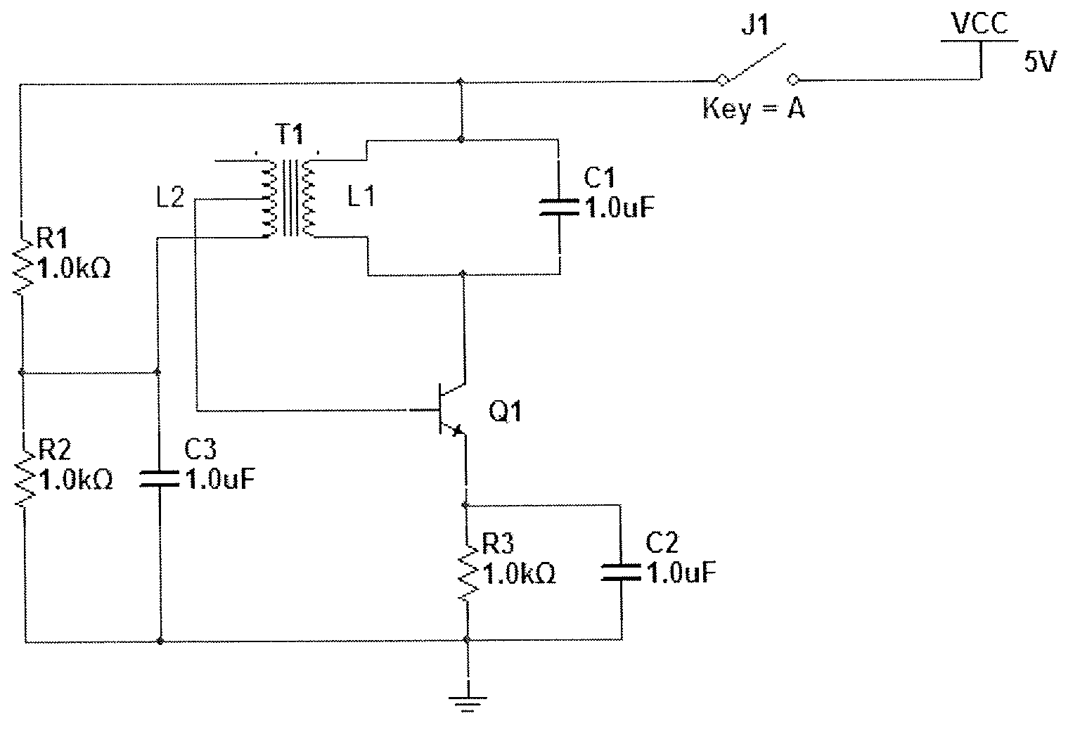
technical field [0001] The present invention relates to sinusoidal oscillators. Background technique [0002] The sine (wave) oscillator is composed of an amplifier circuit and a feedback circuit. The feedback circuit positively feeds back a part of the output voltage of the amplifier circuit to the input terminal of the amplifier circuit, and the oscillation is formed repeatedly. Existing sine wave oscillators include various circuit forms such as transformer-coupled oscillators, three-point oscillators, crystal oscillators, and RC oscillators. [0003] The transformer coupled oscillator circuit diagram is shown in figure 1 As shown, the LC resonance circuit is connected to the collector of the transistor Q1, and the oscillation signal is coupled and fed back to the base set of Q1 through the transformer T1. [0004] The specific working principle of the transformer coupled oscillator is as follows: R1 and R2 provide a suitable bias voltage for Q1 to work in the amplified...

Claims


Application Information

Patent Timeline
IPC IPC(8): H03B5/04
Inventor 王帅覃燕华王华泽王丽郑方磊王杰
Owner UNIV OF SHANGHAI FOR SCI & TECH
Learn More