Electric resistance welding method, electrode welding head using electric resistance welding method and electrode welding head used in electric resistance welding method

A resistance welding and electrode technology, which is applied in the direction of resistance electrode base, resistance welding equipment, roller electrode welding, etc., can solve the problems of reducing the current of the battery pack, increasing the middle transition welding sheet, and fusing of the top weldment 3, so as to improve the output Current, save the effect of transition metal sheet

Inactive Publication Date: 2013-10-02
林青云
View PDF6 Cites 9 Cited by
  • Summary
  • Abstract
  • Description
  • Claims
  • Application Information

AI Technical Summary

Problems solved by technology

[0012] 1) There are certain requirements for the resistance value of the top weldment 3 and the bottom weldment 4, that is, the resistance value of the bottom weldment 4 is much smaller than the resistance value of the top weldment 3, so its scope of application is limited
[0013] 2) When the resistance value of the top weldment 3 is much smaller than the resistance value of the bottom weldment 4, the welding current will be short-circuited by the top weldment 3, and the current will not pass through the bottom weldment 4. Therefore, the top weldment 3 and the bottom weldment cannot be connected 4 welded together
Moreover, the welding current passes through the top-layer weldment 3, and under the action of resistance heat, it is very easy to fuse the top-layer weldment 3 between the two electrodes 1.
[0014] 3) For the state where the top weldment 3 and the bottom weldment 4 are intersected, the balanced gap resistance welding cannot be used
Because, when the two electrodes 1 exert pressure on the top weldment 3, the bottom

Method used


Image

  • Electric resistance welding method, electrode welding head using electric resistance welding method and electrode welding head used in electric resistance welding method
  • Electric resistance welding method, electrode welding head using electric resistance welding method and electrode welding head used in electric resistance welding method
  • Electric resistance welding method, electrode welding head using electric resistance welding method and electrode welding head used in electric resistance welding method

Examples


Embodiment Construction

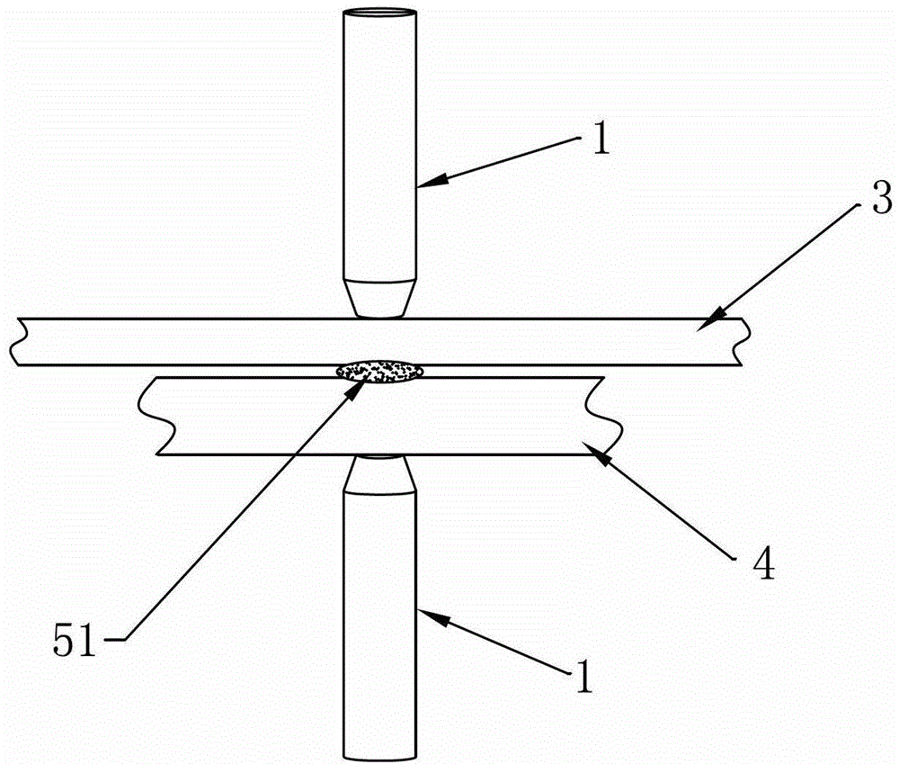
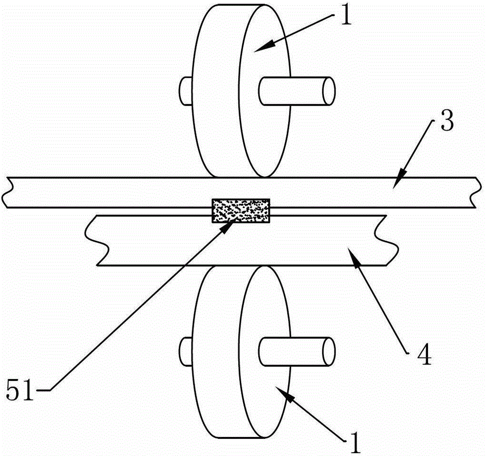
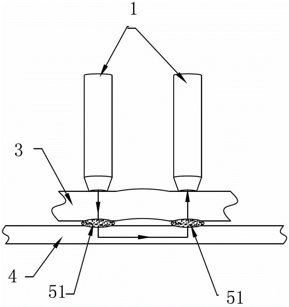
[0060] Such as Figure 4 As shown, the resistance welding method of the present invention is especially suitable for welding between metal wires, wires, wire sheets or sheets in the field of microelectronics. Metal wires, wires, rods, sheets or plates) are lapped together in a way of overlapping or overlapping (that is, the intersection angle between the weldments to be welded can be acute angle, right angle or overlapping up and down, located above the overlapping phase contact The weldment to be welded is called the top weldment 3, the weldment to be welded below is called the bottom weldment 4, the top weldment 3 and the bottom weldment 4 can be single or multiple pieces), and then the two electrodes 1 are pre-pressed on the A current loop is formed on the weldment to be welded, and the two electrodes 1 of the present invention are arranged side by side in the same direction on both sides of the welding position 5 formed by the contact of the top weldment 3 and the bottom w...


PUM


Abstract

The invention discloses an electric resistance welding method, an electrode welding head using the electric resistance welding method and the electrode welding head used in the electric resistance welding method. The electric resistance welding method includes the steps that welding parts to be welded are connected together in a lap joint and a vertically intersected overlaying or overlapping mode, then two electrodes are pressed on a welding part on the top layer in advance in the same direction to form a current loop, pressurizing pieces are arranged between the two electrodes and on the same side as the electrodes, wherein the pressurizing pieces are parallel to the electrodes and can vertically move to press the welding part on the top layer, and in the process of welding, the electric resistance welding method includes the following steps that (1) a power supply of a welding machine is switched on, (2) current generates resistance heat in the welding part on the top layer, and the welding part on the top layer is heated to a fusion or plastic state, (3) the pressurizing pieces pressurize the welding part on the top layer, (4) cooling crystallization is conducted, (5) pressure of the pressurizing pieces and the two electrodes is released, and then the welding parts are taken out. By the adoption of the electric resistance welding method, any metal wire or wire or wire piece or piece in a lap joint state can be welded, the electric resistance welding method is especially used for welding IC card chips and induction coils of the IC card chips and directly welding battery electrodes and copper pieces or copper wires in battery sets and can achieve the good effect.

Description

technical field [0001] The invention relates to a resistance welding method and a used welding head, in particular to a resistance welding method and an electrode welding head in which two electrodes are arranged in parallel in the same direction. Background technique [0002] Resistance welding is to combine the workpieces, apply pressure to different weldments to be welded through two electrodes, and heat them to a molten or plastic state by using the resistance heating effect generated by the current flowing through the contact surface between the weldments to be welded and the adjacent area , so that it forms a method of metal bonding. [0003] There are two main methods of resistance welding commonly used, namely spot welding and seam welding. [0004] spot welding [0005] Such as figure 1 As shown, spot welding is a resistance welding method in which weldments are assembled into lap joints and pressed between two columnar electrodes 1 to melt the base metal by resi...

Claims


Application Information

Patent Timeline
IPC IPC(8): B23K11/11B23K11/30B23K35/04
CPCB23K11/061B23K11/115B23K11/16B23K11/3009B23K11/06B23K11/31B23K11/314B23K2101/38B23K2103/18B23K2103/26B23K11/20H05K3/328Y02E60/10B23K11/30
Inventor 林青云
Owner 林青云
Why Eureka
Try Eureka