Energy saving boiler

A boiler and auxiliary furnace technology, applied in the field of heating equipment, can solve problems such as black smoke, no heat preservation measures, and rapid heat release, etc., to prolong the heat exchange stroke and time, reduce harmful smoke emissions, and increase heat exchange area Effect

Inactive Publication Date: 2015-10-28
中海国利环保科技有限公司
View PDF4 Cites 0 Cited by
  • Summary
  • Abstract
  • Description
  • Claims
  • Application Information

AI Technical Summary

Problems solved by technology

[0004] The existing boilers have the following defects: ①The existing boiler is only a single furnace body, the heat exchange area is small, the heat exchange time is short, and the heat energy utilization rate is low; ②The coal and oxygen cannot be effectively fused, the combustion is insufficient, and it is easy to turn black smoke, low efficiency, and high pollution emissions, especially when the boiler is ignited and coal-filled, the black smoke and harmful smoke are seriously emitted; The inherent calorific value of coal, which fails to effectively utilize high-temperature coal combustion and the interaction between high-temperature heat storage bodies and external substances to produce new high-efficiency combustibles (such as reacting with an appropriate amount of water to produce water gas, etc.) to increase the calorific value; ④Coal combustion During the process, equipment such as air blast, dust removal, and smoke removal machines are used, so that the heat energy of coal combustion does not have sufficient time for heat exchange, and it is discharged into the atmosphere, and consumes a lot of electric energy at the same time; in addition, real-time closed-loop control of combustion is not achieved, resulting in the release of heat energy Too fast, resulting in too fast loss of heat energy; ⑤ There is no insulation measure outside the furnace body, and the heat loss is serious

Method used


Image

  • Energy saving boiler
  • Energy saving boiler

Examples


Embodiment Construction

[0026] The specific implementation manner of the present invention will be described below in conjunction with the accompanying drawings.

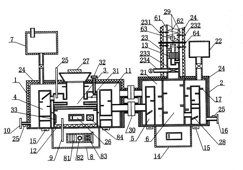
[0027] Such as figure 1As shown, the structure diagram of the energy-saving boiler of the present invention includes a main furnace 1 and an auxiliary furnace 2, the main furnace 1 and the auxiliary furnace 2 are water jacket furnaces, and the outer walls of the main furnace 1 and the auxiliary furnace 2 are coated with an insulating layer 24, Reduce the heat dissipation of the main furnace water jacket 11 and the auxiliary furnace water jacket 21, and further improve heat utilization. The main furnace water jacket 11 and the auxiliary furnace water jacket 21 are connected by a flange 30. The combustion chamber 4 and the secondary combustion chamber 4 are arranged outside the combustion chamber 3 and communicated with the combustion chamber 3. The secondary furnace 2 is provided with a tertiary combustion chamber 5 and a quaternary combust...


PUM


Abstract

The invention discloses an energy-saving boiler which comprises a main boiler body and an auxiliary boiler body, wherein the main boiler body and the auxiliary boiler body are respectively a water jacket boiler body. A water jacket of the main boiler body and a water jacket of the auxiliary boiler body are connected through a flange. A combustor and a secondary combustor are arranged in the main boiler body, and the secondary combustor is arranged outside the combustor in a surrounding mode and is communicated with the combustor. A third-time combustor and a fourth-time combustor are arranged in the auxiliary boiler body, and the third-time combustor is arranged outside the fourth-time combustor in a surrounding mode and is communicated with the fourth-time combustor. The secondary combustor is communicated with the three-time combustor through a flange. A combustion-supporting layer coats the interior of the combustor so that fuller combustion can be achieved. A horizontal convolution gravity smoke exhausting device is arranged in a chimney and used for settling smoke in exhaust gas, and the environmental protection effect is improved. A steam guide pipe is arranged between the combustor and a water compartment, so that water in the water compartment is atomized for forming vapor. The vapor enters the combustor from the steam guide pipe and is reacted with fire coal to produce efficient combustible objects such as water gas and coal tar, and the combustion efficiency is improved.

Description

technical field [0001] The invention relates to heating equipment, in particular to an energy-saving boiler. Background technique [0002] my country is a country with large coal reserves, production, and consumption. It consumes billions of tons of coal every year. The serious problems such as high pollution, high emissions, and waste of resources caused by coal combustion are obvious to all. Its future problems are even more unpredictable; economic development, resource conservation , Environmental protection is related to the success or failure of the great cause of the rejuvenation of the Chinese nation. [0003] At present, the problems caused by various small and medium-sized coal-fired heating boilers used in my country are particularly prominent, and their governance is difficult and cumbersome. It is advisable to use clean energy to support sustainable and effective economic development, but because my country is a country with poor per capita oil and natural gas res...

Claims


Application Information

Patent Timeline
Patent Type & Authority Patents(China)
IPC IPC(8): F24H1/46F24H1/30F24H9/00F24H9/18F23J15/04F23L7/00
Inventor 张宝生刘晓芝王凤兰
Owner 中海国利环保科技有限公司
Why Eureka
Try Eureka