Medical spraying type medicine bottle

A spray type and medicine bottle technology, which is applied in the field of medical spray type medicine bottles, can solve the problems of affecting the liquid discharge, waste of liquid agent, unreasonable structure of the piston tube, etc. Liquid effect improvement effect

Inactive Publication Date: 2013-10-09
苏州汇涵医用科技发展有限公司
View PDF10 Cites 8 Cited by
  • Summary
  • Abstract
  • Description
  • Claims
  • Application Information

AI Technical Summary

Problems solved by technology

However, the patented solution still has the following shortcomings: firstly, because the self-structure of the piston tube (the patent is called the plunger) is unreasonable, a guide seat needs to be added in the valve casing (the patent is called the valve body), The piston tube is guided by the guide seat, so the piston tube rubs against the guide seat during frequent up and down movements, which not only has a large resistance, but also easily produces a gap due to wear, which affects the liquid discharge and even scraps; secondly, because the reset of the piston tube only depends on A small helical spring at the bottom of the valve casing is realized, and the small helical spring is prone to fatigue, so it is difficult to guarantee the reset effect of the piston tube; , the medical personnel need to turn the angle of the wrist, but because the injection direction of the liquid outlet mechanism is difficult to accurately align with the patient's wound, on the one hand, it causes inconvenience to use, and on the other hand, there is a risk of liquid waste; Fourth, due to the complicated structure , thus complicating the manufacture and assembly of

Method used


Image

  • Medical spraying type medicine bottle

Examples


Embodiment Construction

[0017] In order to enable examiners of the Patent Office, especially the public, to more clearly understand the technical essence and beneficial effects of the present invention, the applicant will describe in detail in the form of examples below, but the description of the examples is not intended to describe the solution of the present invention. As a limitation, any equivalent transformations made according to the concept of the present invention that are merely formal rather than substantive should be regarded as the technical solution scope of the present invention.

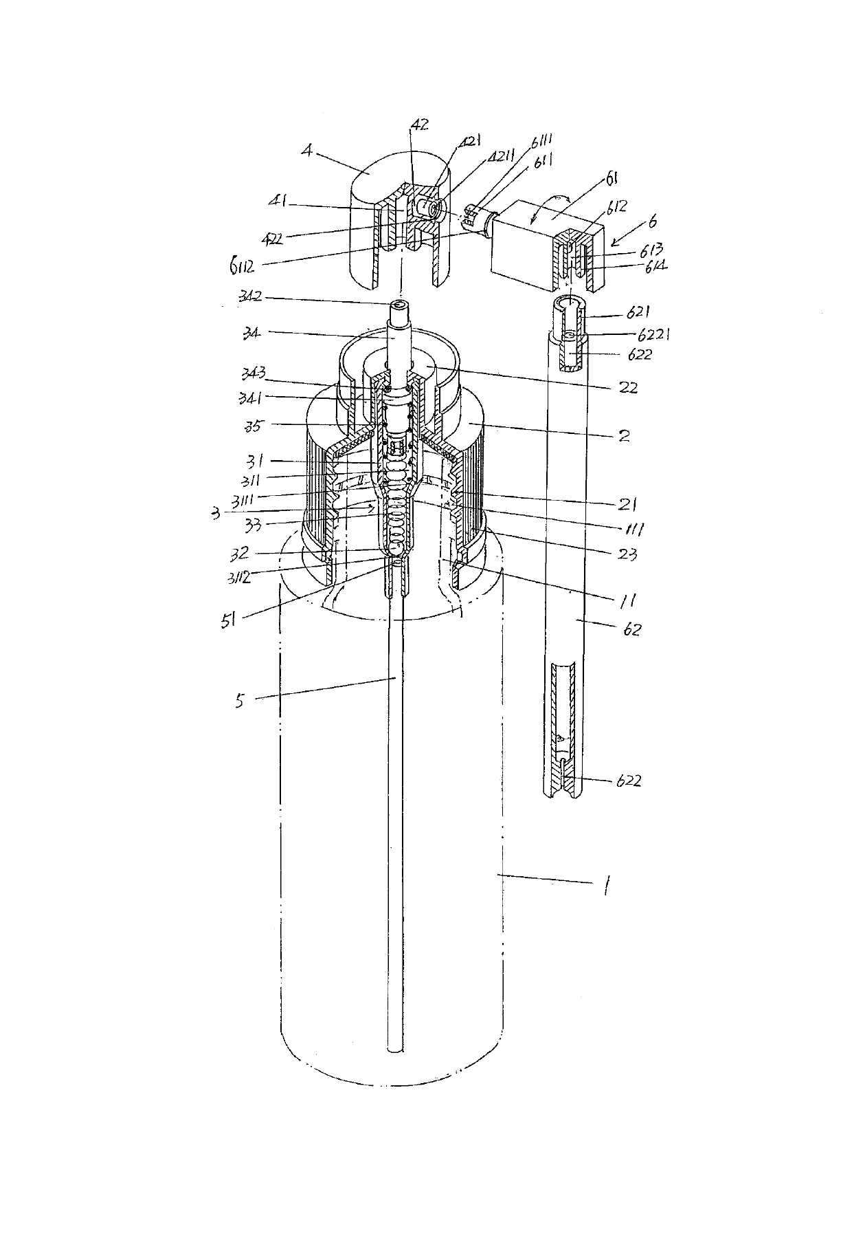
[0018] See figure 1 , A bottle body 1 made of plastic is given. The bottle body 1 has a bottle mouth 11, and a bottle mouth external thread 111 is formed on the outer wall of the bottle mouth 11. A bottle cap 2 (made of plastic) is fitted on the bottle mouth 11, specifically: a bottle cap internal thread 21 is formed on the inner wall of the bottle cap 2, and the bottle cap internal thread 21 is threaded with t...


PUM


Abstract

The invention discloses a medical spraying type medicine bottle and belongs to the technical field of spraying dosing containers. The medical spraying type medicine bottle comprises a bottle body, a bottle cap, a liquid pumping mechanism, a hand pressing gland, a sucker and a liquid outlet mechanism. The liquid pumping mechanism comprises a piston pipe sleeve, a ball valve, a first spring, a piston pipe and a second spring, the upper end of the piston pipe sleeve is fixed with the central position of the bottle cap, the middle of the piston pipe sleeve forms a first narrow indentation step, the lower portion of the piston pipe sleeve forms a second narrow indentation step, the ball valve is arranged in a piston pipe sleeve cavity of the piston pipe sleeve, the middle of the piston pipe forms a piston, the first spring is arranged on the lower portion of the piston pipe sleeve cavity, the second spring is sleeved at the lower end of the piston pipe, and the central position of the hand pressing gland forms a piston pipe matching hole. The liquid outlet mechanism comprises a spraying pipe base and a spraying pipe, a liquid through hole is formed in the spraying pipe base, a flow diversion pipe joint is arranged on one side of the spraying pipe base, a flange is formed on the flow diversion pipe joint, the flow diversion pipe joint forms a flow diversion pipe cavity, and the sucker is in matched connection with the lower end of the piston pipe sleeve. The liquid pumping effect is improved, the liquid spraying speed is improved, medicine liquid waste is avoided, and the structure is simple.

Description

Technical field [0001] The invention belongs to the technical field of spray drug delivery containers, and specifically relates to a medical spray medicine bottle. Background technique [0002] The function of the medical spray bottle is to spray the medical liquids filled in the bottle cavity, such as wound care solution, hemostatic agent, disinfectant and wound cleaning solution, etc., onto the surface of the patient’s wound. This type of bottle can be described in Chinese patent documents. There are a lot of them, such as CN2552860Y (a kind of medicine bottle), CN201286921 (a medicine bottle), CN202621357U (a sprayer), and so on. [0003] Among the patents not listed above, the structure of CN2552860Y is relatively reasonable, which not only overcomes the deficiencies of the invention patent application number 99105364.5, but also reflects the technical effect described in the second-to-last paragraph on page 2 of the specification. However, the patented solution still has the ...

Claims


Application Information

Patent Timeline
Patent Type & Authority Applications(China)
IPC IPC(8): A61J1/05A61M11/02
Inventor 冯永良冯胜权
Owner 苏州汇涵医用科技发展有限公司
Why Eureka
Try Eureka