Waste gas recovery system for mucilage glue production

A waste gas recovery and viscose technology, which is applied in the separation of dispersed particles, carbon disulfide, chemical instruments and methods, etc., can solve the problems of atmospheric and environmental pollution, inability to effectively treat waste gas, and direct discharge of waste gas failing to meet the emission standards, and achieve collection Good effect and low cost investment

Inactive Publication Date: 2013-10-09
JIANGSU SHENJIANG ENVIRONMENT TECH
View PDF0 Cites 4 Cited by
  • Summary
  • Abstract
  • Description
  • Claims
  • Application Information

AI Technical Summary

Problems solved by technology

The direct emission of the above-mentioned exhaust gas does not meet the national emission standards, which will cause pollution to the atmosphere and the environment
Existing waste gas treatment devices cannot effectively treat waste gas containing H2S and CS2

Method used


Image

  • Waste gas recovery system for mucilage glue production

Examples


Embodiment Construction

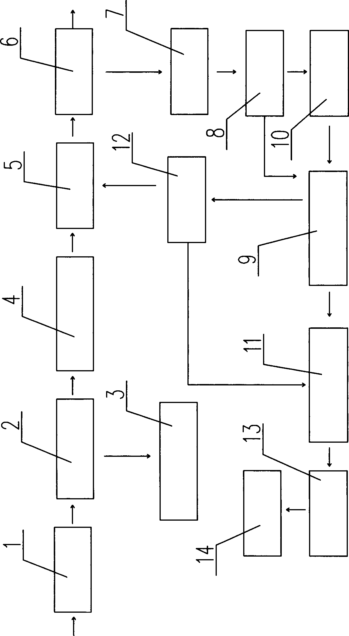
[0008] The specific content of the present invention will be described in detail below in conjunction with the accompanying drawings and specific embodiments.

[0009] Such as figure 1 As shown, the viscose production exhaust gas recovery system includes: alkali washing blower 1, the alkali washing tank 2 connected with the alkali washing blower 1, the Na 2 S, NaHS storage tank 3 and washing tower 4, the blower fan 5 that is connected with described washing tower 4, the activated carbon adsorption tank 6 that is connected with described blower fan 5, the evaporator 7 that is connected with described activated carbon adsorption tank 6, The first condenser 8 that is connected with the evaporator 7, the gas-liquid separator 9 and the second condenser 10 that are connected with the first condenser 8, the specific gravity that is connected with the gas-liquid separator 9 Separator 11 and safety tank 12, the aftercooler 13 connected with the specific gravity separator 11 and the CS...


PUM


Abstract

The invention discloses a waste gas recovery system for mucilage production with a good treatment effect. The recovery system comprises an alkali cleaning fan, an alkaline bath connected with the alkali cleaning fan, an Na2S and NaHS storage tank and a water scrubber which are connected with the alkaline bath, a draught fan connected with the water scrubber, an activated carbon adsorption tank connected with the draught fan, an evaporator connected with the activated carbon adsorption tank, a first condenser connected with the evaporator, a gas-liquid separator and a second condenser which are connected with the first condenser, a specific gravity separator and a safety can which are connected with the gas-liquid separator, and an after-cooler connected with the specific gravity separator, and a CS2 storage tank connected with the after-cooler. The second condenser is connected with the gas-liquid separator, and the safety can is connected with the specific gravity separator and the draught fan.

Description

technical field [0001] The invention relates to an industrial waste gas treatment device, in particular to a viscose production waste gas recovery system. Background technique [0002] During the production process of viscose fiber, a large amount of waste gas containing H2S and CS2 will be produced. These waste gases mainly overflow at the following process points, namely: the exhaust of the yellowing machine, the waste gas of the spinning machine, drafting and cutting machine, and the second bath tank after condensation Exhaust gas after condensation from the device, fluff forming exhaust gas, scouring machine-washing exhaust gas, acid station degassing and exhaust gas from each bath. Due to the characteristics of the viscose fiber production process, the composition of the exhaust gas at each overflow point is also different: the exhaust gas H2S and CS2 concentrations from the spinning machine are both high, and the exhaust gas degassed from the acid station has the highe...

Claims


Application Information

Patent Timeline
Patent Type & Authority Applications(China)
IPC IPC(8): B01D53/74B01D53/78B01D53/52C01B31/26C01B32/72
Inventor 聂庭江
Owner JIANGSU SHENJIANG ENVIRONMENT TECH
Why Eureka
Try Eureka