Method for controlling heat crack and residual stress of Fe-based fusion-repair layer via ultrasonic impact

A technology of residual stress and ultrasonic impact, applied in the field of welding, can solve the problems of workpiece life and post-weld processing, difficult to use post-weld heat treatment, cracks, etc.

Inactive Publication Date: 2013-10-09
LIAONING TECHNICAL UNIVERSITY +1
View PDF1 Cites 5 Cited by
  • Summary
  • Abstract
  • Description
  • Claims
  • Application Information

AI Technical Summary

Problems solved by technology

Because these differences will affect the thermal cycle process and crystallization conditions during the surfacing process, resulting in increased welding stress and reduced joint quality
Fe-based self-fluxing alloy powder cladding process is prone to some quality defects, such as pores, inclusions, cracks, composition segregation, etc.
The surface hardness of the cladding layer is high, and the crack resistance is poor. The alloy powder contains high carbon, silicon and boron elements, which form alloy compounds with other alloy elements. These alloy compounds have high hardness, poor toughness, and tend to produce cracks. Big
And there is a large residual stress after welding, which has a serious impact on the life of the workpiece and post-welding processing
[0004] The solution to cracks in the cladding layer is basically based on the addition of alloying elements and the adjustment of the welding process, but it is difficult to fundamentally solve the problem of cracks in the cladding layer in actual welding production
The adjustment of welding residual stress is difficult to adopt the method of post-weld heat treatment due to the difference in material parameters between the cladding layer and the base material.
Therefore, these processes have some effects in controlling the thermal cracking and residual stress of the Fe-based self-fluxing alloy powder repair layer, but they all have limitations and low efficiency.

Method used


Image

  • Method for controlling heat crack and residual stress of Fe-based fusion-repair layer via ultrasonic impact
  • Method for controlling heat crack and residual stress of Fe-based fusion-repair layer via ultrasonic impact

Examples


Embodiment 1

[0021] The fused layer of Fe302 self-fluxing alloy powder with a thickness of 1mm was subjected to ultrasonic impact treatment. It includes the following steps:

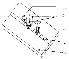
[0022] The first step: the installation of ultrasonic impact guns for controlling thermal cracking: install two rows of ultrasonic impact guns for controlling thermal cracking at a distance of 35mm from the front welding torch. The ultrasonic impact gun is perpendicular to the surface of the workpiece to be processed. The diameter of the impact head is 3mm. The hardness of the impact needle should be no less than 55HRC;

[0023] Step 2: Installation of the ultrasonic impact gun to control the residual stress: Install an ultrasonic impact gun to control the residual stress 100mm from the front welding torch. The ultrasonic impact gun is perpendicular to the surface of the workpiece to be processed. The diameter of the impact head is 5mm. The hardness of the needle should be no less than 55HRC;

[0024] The third step: for ...

Embodiment 2

[0028] Ultrasonic impact treatment was performed on the Fe302 self-fluxing alloy powder fused layer with a thickness of 0.5mm. It includes the following steps:

[0029] The first step: the installation of ultrasonic impact guns for controlling thermal cracking: install two rows of ultrasonic impact guns for controlling thermal cracking at a distance of 40mm from the front welding torch. The ultrasonic impact gun is perpendicular to the surface of the workpiece to be processed, and the impact head diameter is 3mm The hardness of the impact needle should be no less than 55HRC;

[0030] Step 2: Installation of the ultrasonic impact gun that controls the residual stress: Install an ultrasonic impact gun that controls the residual stress at a distance of 110mm from the front welding torch. The ultrasonic impact gun is perpendicular to the surface of the workpiece to be processed. The diameter of the impact head is 5mm. The hardness of the needle should be no less than 55HRC;

[0031] St...

Embodiment 3

[0035] The 3mm thickness of Fe302 self-fluxing alloy powder fused layer was subjected to ultrasonic impact treatment. It includes the following steps:

[0036] The first step: the installation of ultrasonic impact guns for controlling thermal cracking: install two rows of ultrasonic impact guns for controlling thermal cracking at a distance of 37mm from the front welding torch. The ultrasonic impact gun is perpendicular to the surface of the workpiece to be processed. The diameter of the impact head is 4mm. The hardness of the impact needle should be no less than 55HRC;

[0037] Step 2: Installation of the ultrasonic impact gun that controls the residual stress: Install an ultrasonic impact gun that controls the residual stress at a distance of 120mm from the front welding torch. The ultrasonic impact gun is perpendicular to the surface of the workpiece to be processed. The diameter of the impact head is 6mm. The hardness of the needle should be no less than 55HRC;

[0038] Step 3:...


PUM

PropertyMeasurementUnit
diameteraaaaaaaaaa
diameteraaaaaaaaaa
thicknessaaaaaaaaaa

Abstract

The invention discloses a method for controlling the heat crack and residual stress of a Fe-based fusion-repair layer via an ultrasonic impact, which belongs to the field of process technology. The method comprises the following steps of: step 1, controlling installation for an ultrasonic impact gun for heat crack; step 2, controlling installation for an ultrasonic impact gun for residual stress; and step 3, performing impact treatment on the Fe-based self-fluxing alloy powder fusion-repair layer having a thickness of 0.5-3 mm during a welding process. The method disclosed by the invention has the following advantages that (1) the heat crack tendency of the Fe-based self-fluxing alloy powder fusion-repair layer caused by the difference of material parameters with matrix metal can be suppressed; (2) the surface residual tensile stress of the fusion-repair layer can be reduced, and the working life of a workpiece can be prolonged simultaneously; and (3) the crystalline grain diameter of the fusion-repair layer can be reduced, and the ductility and toughness of the fusion-repair layer can be improved based on improvement for the wear resistance of the fusion-repair layer.

Description

Technical field [0001] The invention belongs to the technical field of welding, and specifically relates to a method for controlling the thermal cracking and residual stress of an Fe-based fusion repair layer by ultrasonic impact. Background technique [0002] The fatigue fracture, wear, corrosion and oxidation of materials generally start from the surface, and the damage and loss caused by this are very alarming. With only corrosion, the world loses more than 100 million tons of metal every year. Therefore, the use of various surface strengthening technologies to improve the surface properties of materials and strengthen the surface protection of materials is of great significance to the fatigue damage, wear and corrosion of materials. [0003] However, if the composition of the surfacing material is different from that of the base material, a transition layer whose structure and properties are different from those of the base material or the surfacing layer must be produced durin...

Claims


Application Information

Patent Timeline
Patent Type & Authority Applications(China)
IPC IPC(8): C21D7/06
CPCY02P10/20
Inventor 时海芳刘冲张勇石荟琦任鑫綦秀玲周嵩然安婷婷
Owner LIAONING TECHNICAL UNIVERSITY
Why Eureka
Try Eureka