Longitudinally-sealed underwater cable manufacturing method

A manufacturing method and optical cable technology, applied in the direction of fiber mechanical structure, etc., can solve the problems of complex underwater optical cable structure, poor longitudinal water tightness, high manufacturing cost, etc., achieve simple structure, good longitudinal water tightness, and improve product quality and reliability Effect

Active Publication Date: 2013-10-16
JIANGSU HONGTU HIGH TECHNOLOGY STOCK CO LTD
View PDF5 Cites 3 Cited by
  • Summary
  • Abstract
  • Description
  • Claims
  • Application Information

AI Technical Summary

Problems solved by technology

[0006] The technical problem to be solved by the present invention is to overcome the defects of the existing underwater optical cable such as complex structure, high manufacturing cost, large cable diameter, poor longitudinal water tightness, etc., and provide an optical cable

Method used


Image

  • Longitudinally-sealed underwater cable manufacturing method
  • Longitudinally-sealed underwater cable manufacturing method
  • Longitudinally-sealed underwater cable manufacturing method

Examples


Embodiment 1

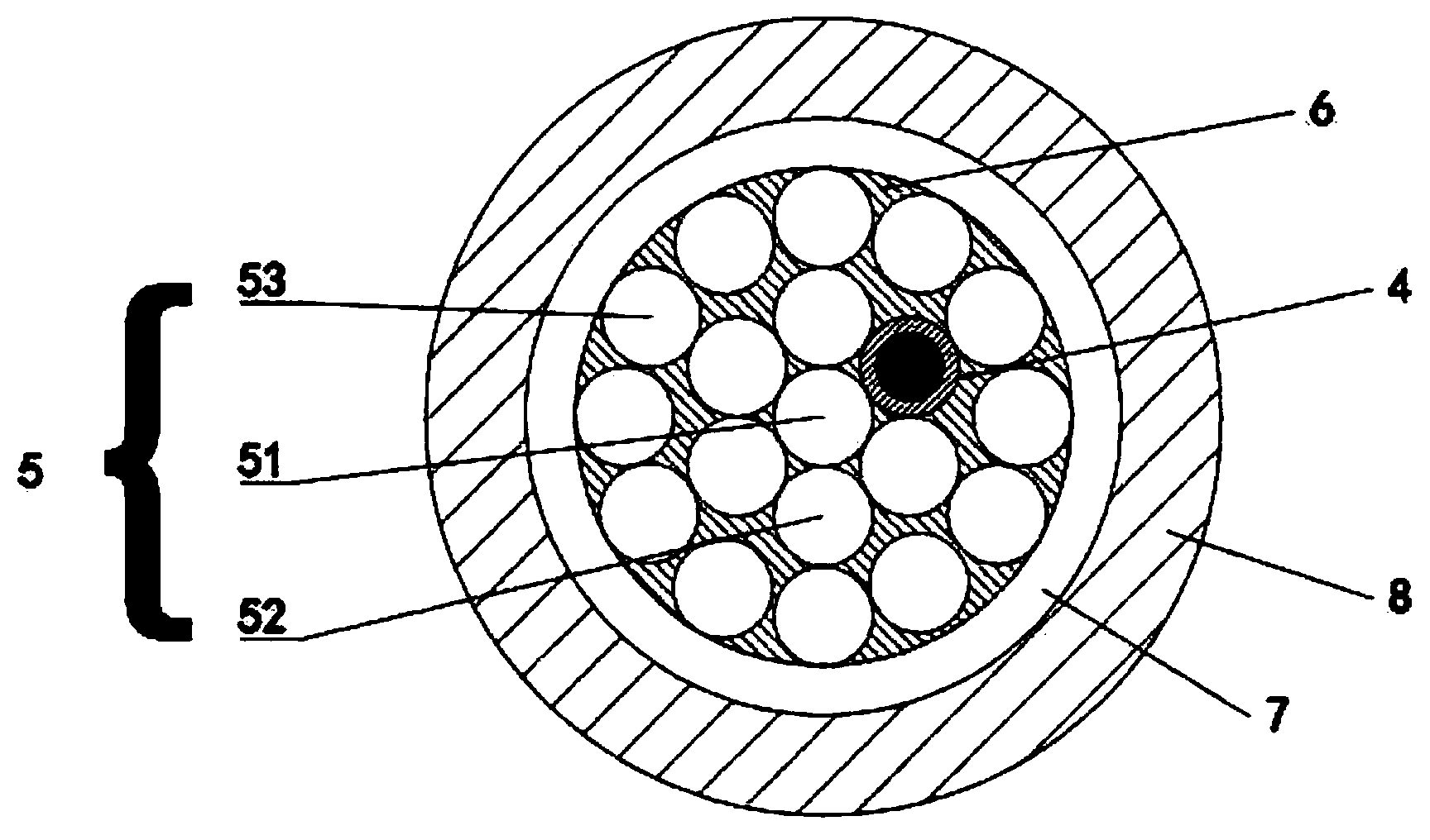
[0033] Fiber optic cable contains:

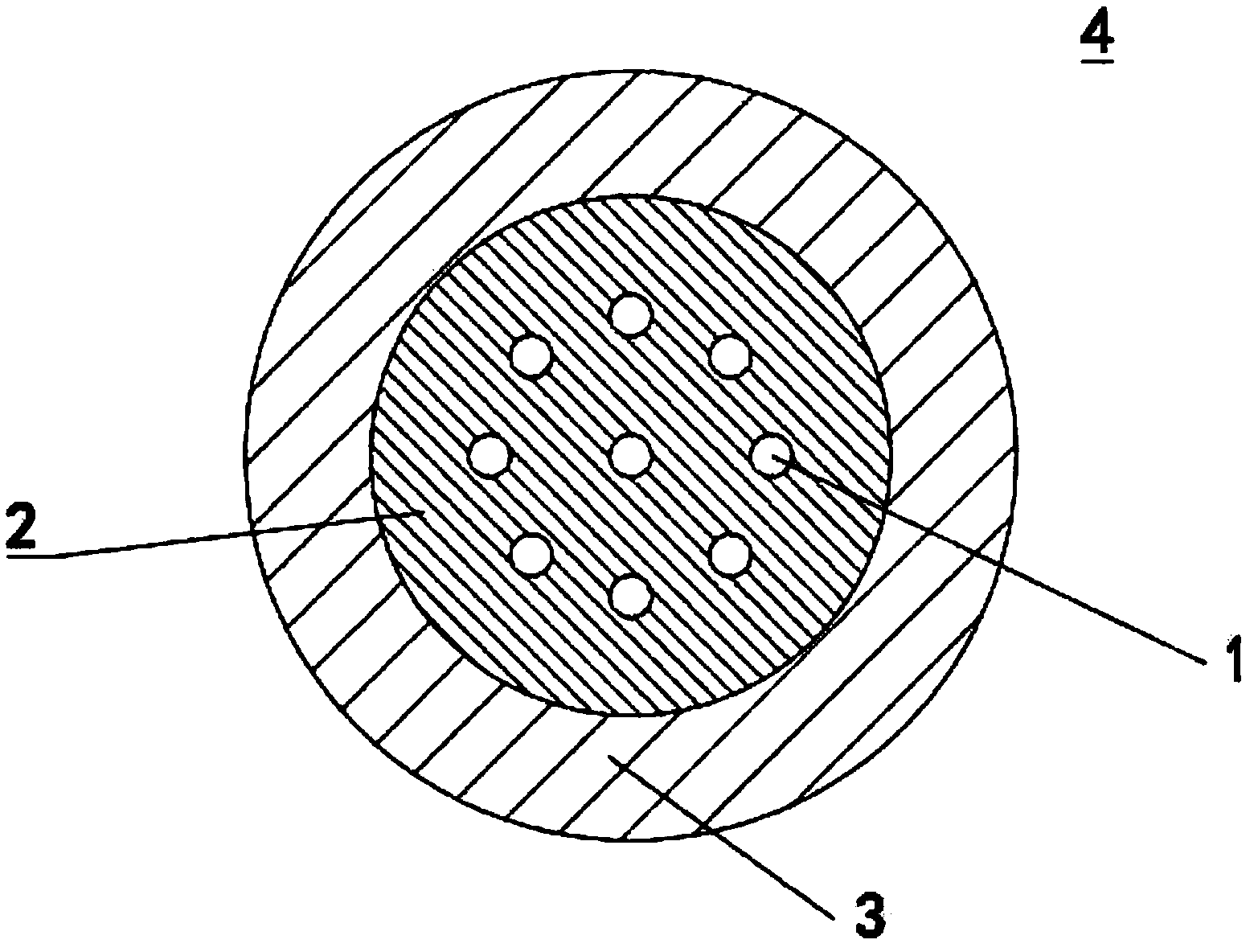
[0034] 2 optical units 4, each optical unit 4 contains: 24 optical fibers 1, hydrogen-absorbing fiber paste 2, stainless steel tube 3 with a diameter of 3 mm;

[0035] The middle line 51 is: a steel wire with a diameter of 3mm;

[0036] The strengthening device 52 between optical units includes: 4 steel wires with a diameter of 3mm;

[0037] The external strengthening device 53 of the light unit includes: 12 steel wires with a diameter of 3mm;

[0038] The water-blocking and anti-corrosion material 6 is made of hot melt adhesive;

[0039] The waterproof sheath includes: wrapping tape 7, polyurethane sheath 8.

[0040] The preparation method comprises the following steps:

[0041] The first step is to wrap the optical fiber 1 and the hydrogen-absorbing fiber paste 2 inside the stainless steel tube 3 by conventional techniques to make the optical unit 4 .

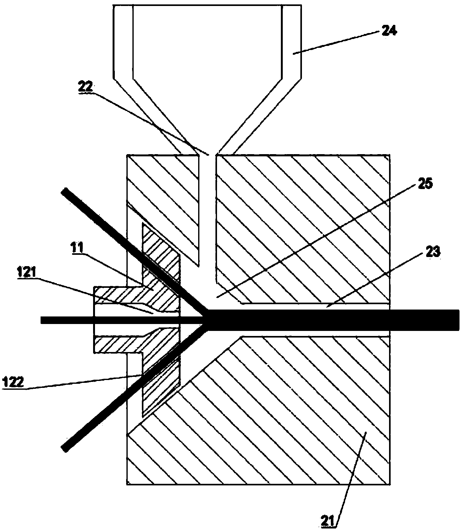
[0042] The second step is to melt the hot melt adhesive and keep it at a constant...

Embodiment 2

[0056] Fiber optic cable contains:

[0057] 1 optical unit 4, each optical unit 1 contains: 12 optical fibers 1, hydrogen-absorbing fiber paste 2, stainless steel tube 3 with a diameter of 2.8 mm;

[0058] The middle line 51 is: a steel wire with a diameter of 2.8mm;

[0059] The strengthening device 52 between optical units includes: 5 steel wires with a diameter of 2.8 mm;

[0060] The water-blocking and anti-corrosion material 6 is made of hot melt adhesive;

[0061] The waterproof sheath includes: wrapping tape 7, polyethylene sheath 8.

[0062] Repeat the preparation method of Embodiment 1 in combination with the rotating mold, except that there is no external reinforcing device 53 for the light unit in this embodiment, so the sixth step above is omitted. The preparation method comprises the following steps:

[0063] The first step is to prefabricate the light unit;

[0064] In the second step, the hot melt adhesive is melted in the constant temperature heating devic...


PUM

PropertyMeasurementUnit
Diameteraaaaaaaaaa
Diameteraaaaaaaaaa

Abstract

The invention provides a divisional application of a parent application 201210031989.3. The invention discloses a longitudinally-sealed underwater cable. The longitudinally-sealed underwater cable includes an optical unit, a reinforcing device and a waterproof sheath. Gaps between the optical units, the reinforcing device and the waterproof sheath are filled with waterproof and anti-corrosion material. The reinforcing device includes a central line and an inter-optical-unit reinforcing device including a plurality of reinforcing pieces having round sections. The optical unit and the reinforcing pieces having the round sections are disposed around the central line in a concentrically ringed manner. The waterproof and anti-corrosion material is in a solid state at normal temperature. The longitudinally-sealed underwater cable is simple in structure, small in cable diameter and good in longitudinal water-tightness, and has advantages of good corrosion resistance, tensile resistance and pressure resistance and the like. Product quality and reliability of the longitudinally-sealed underwater cable are improved and manufacturing cost of the longitudinally-sealed underwater cable is reduced. The invention also discloses a manufacturing method of the longitudinally-sealed underwater cable.

Description

[0001] The patent application for the present invention is a divisional application. The application number of the original application is 201210031989.3, the application date is February 14, 2012, and the title of the invention is: longitudinally sealed underwater optical cable and its preparation method. technical field [0002] The invention belongs to the technical field of optical fiber communication, monitoring signal transmission or temperature measurement system, and specifically relates to a device for preparing a longitudinally sealed underwater optical cable and a preparation method thereof. Background technique [0003] Underwater optical cables are mainly used in underwater environmental conditions in rivers, lakes, shallow seas, coastal areas, islands and other areas. The underwater optical cable is suitable for working underwater all year round and needs to meet certain conditions, such as: good moisture resistance and corrosion resistance and good compression...

Claims


Application Information

Patent Timeline
IPC IPC(8): G02B6/44
Inventor 毛文沛施春光
Owner JIANGSU HONGTU HIGH TECHNOLOGY STOCK CO LTD
Why Eureka
Try Eureka