Low-power-consumption variable gain amplifier

A gain amplifier, low power consumption technology, used in differential amplifiers, DC coupled DC amplifiers, gain control, etc.

Active Publication Date: 2013-10-16
HUAQIAO UNIVERSITY
View PDF4 Cites 7 Cited by
  • Summary
  • Abstract
  • Description
  • Claims
  • Application Information

AI Technical Summary

Problems solved by technology

[0007] By changing the output load resistor R D Adjusting the VGA gain will cause the common-mode level of the differential output to change with the load, so that the post-stage circuit cascaded with the VGA cannot work normally.
The output common mode can be stabilized by the common mode feedback loop (CMFB), but this will greatly increase the complexity of the circuit design, increase the power consumption of the entire VGA, and need to add additional resistors to detect the output common mode voltage, consuming large chip area

Method used


Image

  • Low-power-consumption variable gain amplifier
  • Low-power-consumption variable gain amplifier
  • Low-power-consumption variable gain amplifier

Examples


Embodiment 1

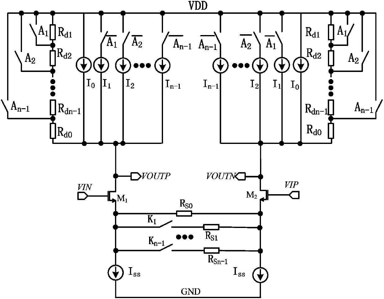
[0058] Such as figure 2 As shown, the present invention is a low power consumption variable gain amplifier without a common-mode feedback circuit, and the variable gain amplifier includes a differential common source amplifying unit, a variable load resistor array R d1 ~R dn-1 , the first digital control switch array A 1 ~A n-1 , the second digital control switch array Variable Current Source Array I 1 ~I n-1 , variable source feedback resistor array R s1 ~R sn-1 , switch array K 1 ~K n-1 , fixed current source I 0 and I SS , fixed resistance R d0 and R s0 ,

[0059] The differential common-source amplifying unit includes a parallel first differential amplifier tube M1 and a second differential amplifier tube M2 for receiving and amplifying differential signals,

[0060] The variable load resistor array R d1 ~R dn-1 and a fixed resistor R d0 connected in series to the supply voltage V DD and the drain of the differential common source amplifying unit, the v...

Embodiment 2

[0082] Based on the principle and working mode of the above-mentioned amplifier circuit, the present invention prefers a more specific preferred embodiment to further illustrate the implementation of the present invention.

[0083] refer to image 3 As shown, as a more specific preferred embodiment, the present invention is a low power consumption variable gain amplifier without a common-mode feedback circuit, taking n=2, then the variable load resistance array R d1 ~R dn-1 including resistor R d1 , then the load resistance consists of the resistor R d0 and resistor R d1 , the resistor R d0 Including two symmetrical parts, namely the resistance A_R d0 and resistor B_R d0 , and the resistance R d0 Resistance value = resistance A_R d0 Resistance value = resistance B_R d0 Resistor value, the resistor A_R d0 is resistor R5, the resistor B_R d0 is resistor R6, the resistor R d1 Including two symmetrical parts, namely the resistance A_R d1 and resistor B_R d1 , and the...


PUM


Abstract

The invention relates to the field of analogue integrated circuits, and discloses a low-power-consumption variable gain amplifier. The low-power-consumption variable gain amplifier comprises a differential common-source amplification unit, variable load resistor arrays Rd1-Rdn-1, digital control switch arrays A1-An-1, variable current source arrays I1-In-1, variable-source feedback resistor arrays Rs1-Rsn-1, switch arrays K1-Kn-1, a fixed current source I0, a fixed current source ISS, a fixed resistor Rd0 and a fixed resistor Rs0, wherein effective resistance values in the variable load resistor arrays Rd1-Rdn-1 are controlled through the digital control switch arrays A1-An-1, current sources in the variable current source arrays I1-In-1 are controlled through the digital control switch arrays, effective resistance values in the variable-source feedback resistor arrays Rs1-Rsn-1 are controlled through the switch arrays K1-Kn-1, and the output common mode voltage of the variable gain amplifier meets the following conditional equation of . By means of the design mode, the common mode is stably output, a common mode feedback circuit is removed at the same time, and accordingly the complexity and power consumption of the circuits are reduced.

Description

technical field [0001] The invention relates to the field of analog integrated circuits, in particular to a low-power consumption variable gain amplifier applied in a short-distance wireless receiver and transmitter without a common-mode feedback circuit. Background technique [0002] The variable gain amplifier (VGA) is a key component of the automatic gain control system (AGC). It is mainly used in the wireless receiver and transmitter system. It can amplify or attenuate the signal according to the strength of the signal, so as to avoid the When the receiver is blocked or the signal is too weak, the signal is lost, which is conducive to improving the dynamic range of the entire wireless receiver-transmitter system. In the AGC system, the design performance of VGA directly affects the selectivity and sensitivity of AGC. In the structure of modern receivers, the detection of signal strength is usually carried out in the digital domain, which makes the digitally controlled V...

Claims


Application Information

Patent Timeline
Patent Type & Authority Applications(China)
IPC IPC(8): H03F3/45H03G3/20
Inventor 杨骁张俏蒋本福凌朝东黄炜炜莫冰
Owner HUAQIAO UNIVERSITY
Why Eureka
Try Eureka