
System comprising an electrically excited machine

A technology of excitation winding and potential, applied in the field of operating the system according to the present invention, can solve the problem that the battery system does not provide a constant DC voltage and the like

Active Publication Date: 2013-10-16
ROBERT BOSCH GMBH
View PDF4 Cites 1 Cited by
  • Summary
  • Abstract
  • Description
  • Claims
  • Application Information

AI Technical Summary

Problems solved by technology

[0005] Unlike conventional systems, no constant DC voltage is provided at the output of the battery system, which can be used, for example, to feed the field winding of an externally excited motor

Method used


Image

  • System comprising an electrically excited machine
  • System comprising an electrically excited machine
  • System comprising an electrically excited machine

Examples


Embodiment Construction

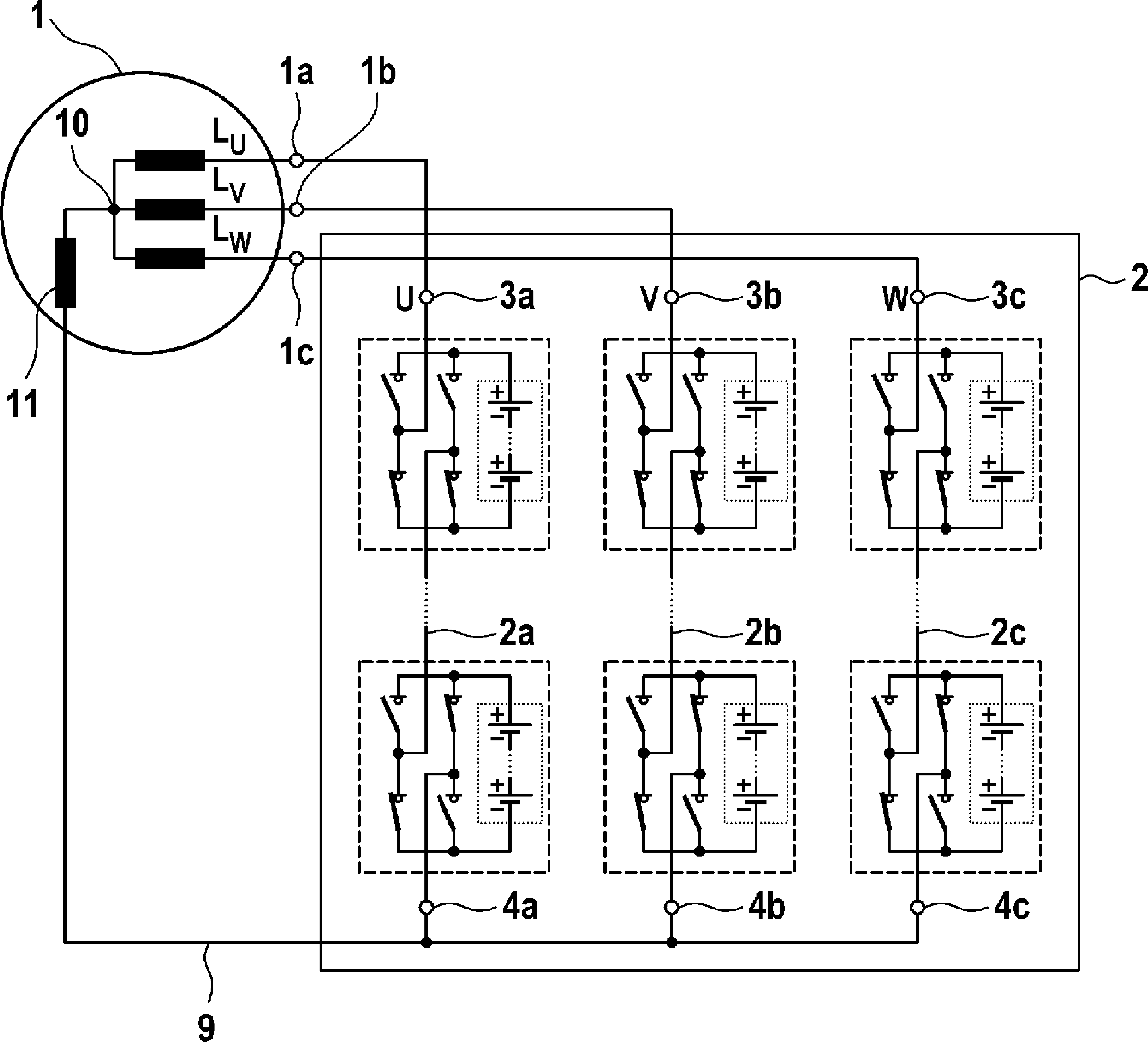
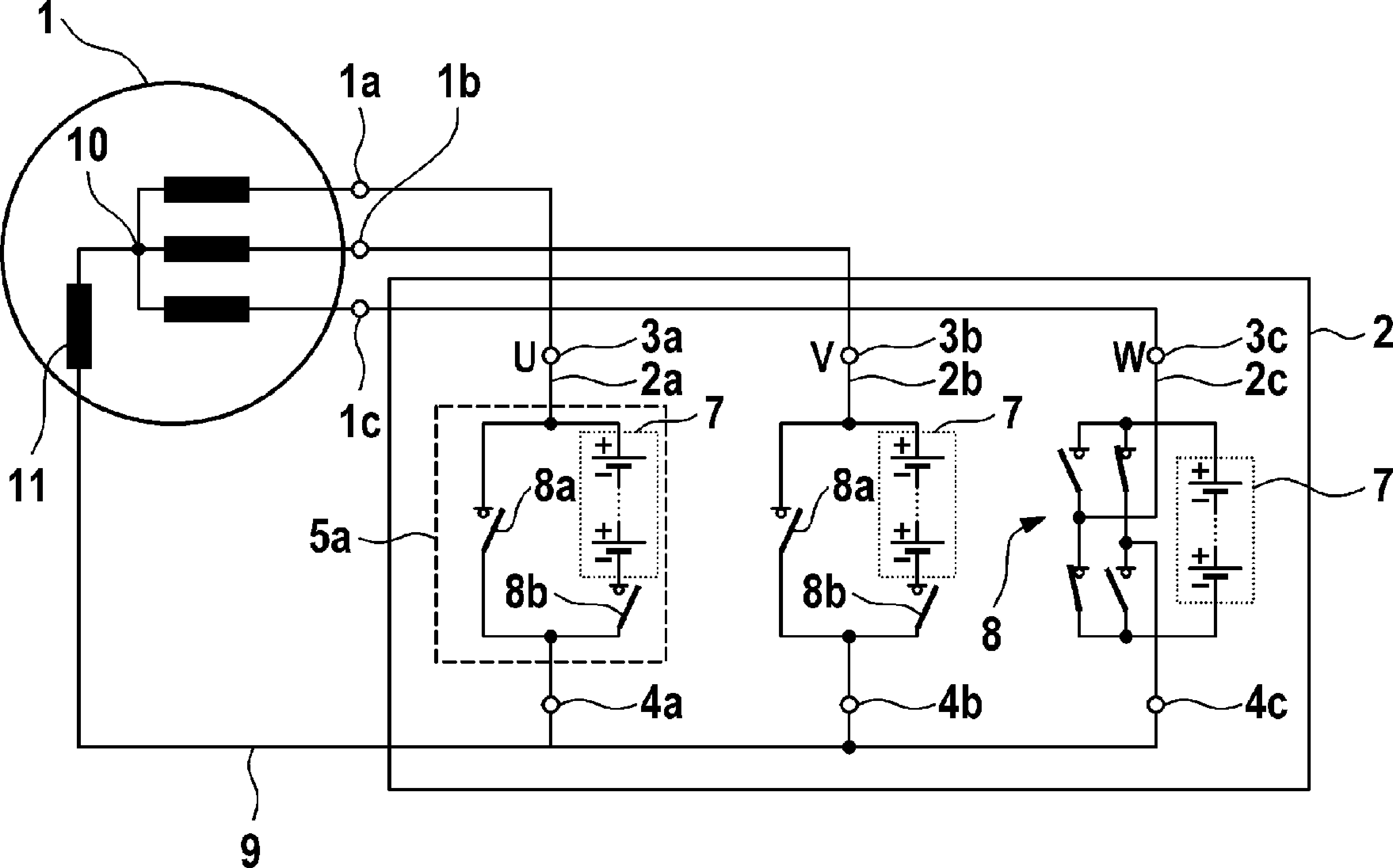
[0017] figure 2 A system with an electric machine 1 and a controllable energy store 2 is shown. The electric machine 1 is shown by way of example as a three-phase electric machine 1 , which is supplied with energy via a first controllable energy store 2 . The first controllable energy store 2 comprises three energy supply branches 2a, 2b, 2c, which are connected on one side via terminals 4a, 4b, 4c to a reference potential 9 (reference busbar), said reference In the embodiment shown, the potential 9 conducts an average potential with respect to the phases U, V, W of the electric machine 1 , and the energy supply branches are connected on the other side to the respective phases U, V, W of the electric machine 1 . In this case, the terminal 3a of the first energy supply branch 2a is coupled to the first phase terminal 1a of the electric machine 1, the terminal 3b of the second energy supply branch 2b is coupled to the second phase terminal 1b of the electric machine 1, and the...


PUM


Abstract

The invention relates to a system comprising an n-phase separately excited electrical machine (1), with n = 1, a controllable first energy store (2) which has n parallel energy supply branches (2a, 2b, 2c), every energy supply branch (2a, 2b, 2c) comprising a first connection (3a, 3b, 3c) that is connected to a respective phase connection (1a, 1b, 1c) of the electrical machine (1), and a second connection (4a, 4b, 4c) that is connected to a common reference bus (9), said reference bus (9) being connected to the neutral point (10) of the electrical machine (1) via a field winding (11) of the electrical machine (1).

Description

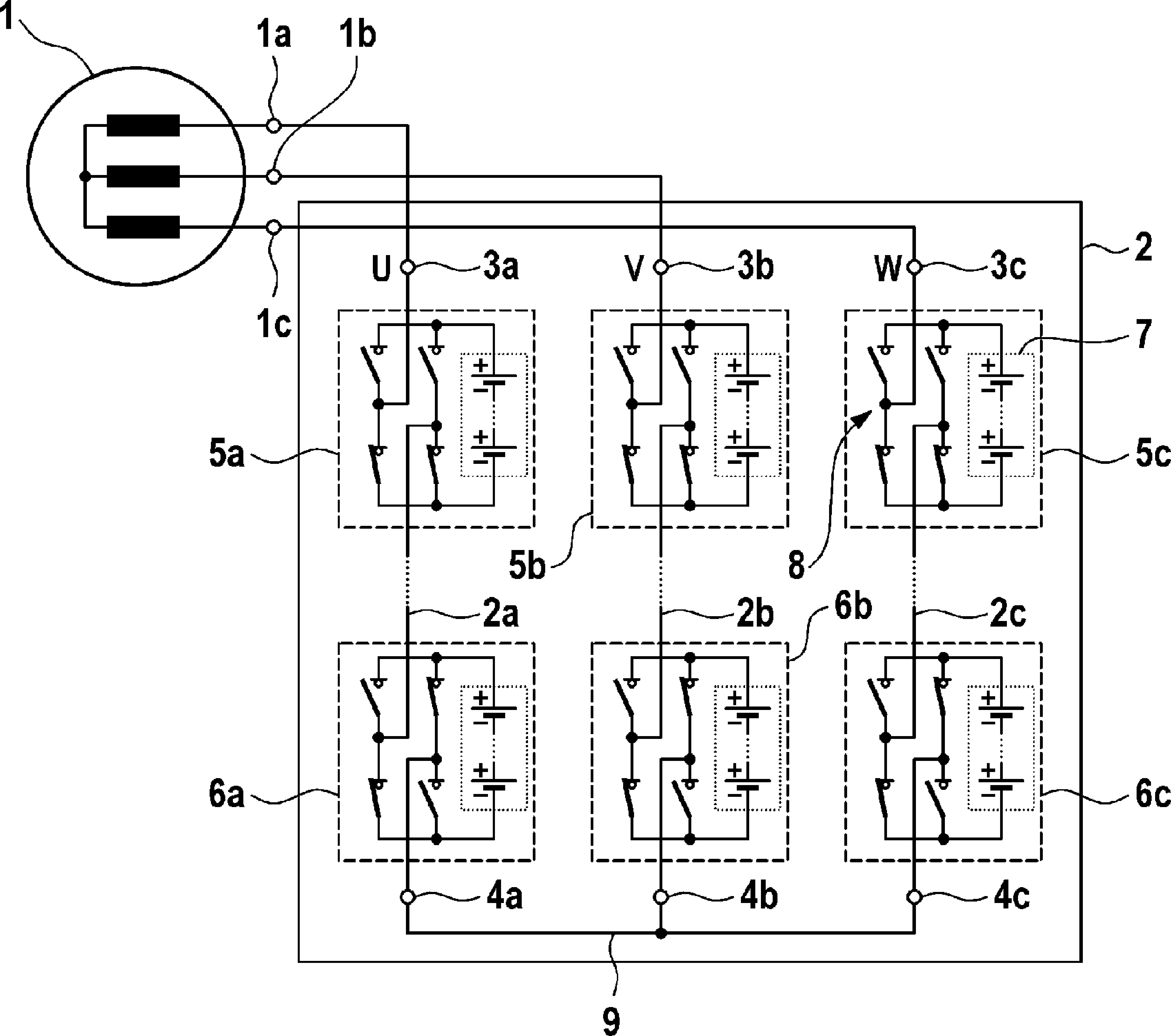
technical field [0001] The invention relates to a system with an electric exciter, which is controlled and supplied with electrical energy by means of a first controllable energy store, and to a method for operating the system according to the invention. Background technique [0002] It has been shown that electronic systems combining new energy storage technology with electric drive technology will be increasingly used in the future both in stationary applications such as wind power plants and in vehicles such as hybrid or electric vehicles. In routine applications, such as in figure 1 As shown in , an electric machine 101 , for example embodied as an induction machine, is controlled via a converter in the form of a pulse-pulse inverter 102 . Characteristic for such a system is a so-called direct voltage intermediate circuit 103 , via which an energy store 104 , generally a traction battery, is connected to the direct voltage side of the pulse inverter 102 . In order to b...

Claims


Application Information

Patent Timeline
Patent Type & Authority Applications(China)
IPC IPC(8): H02P9/30H02M7/49
CPCH02M7/49H02J7/1492H02J2007/0067H02J7/0065H02P6/14Y02T10/7055B60L11/1803Y02E10/766Y02T10/7005H02J7/0024H02P25/021H02J2007/0059Y02T10/70H02P2209/01Y02T10/642H02M2007/4835Y02T10/92H02P25/024B60L50/51H02J2207/20H02J2310/48H02J2300/28H02J7/0025Y02T10/64H02M7/4835Y02E10/76
Inventor P.福伊尔施塔克E.魏森博恩M.凯斯勒
Owner ROBERT BOSCH GMBH
Learn More