Contact box with built-in over-temperature protection device

An overheating protection and contact box technology is applied in the field of contact boxes to achieve the effects of ensuring electrical safety, simple structure and strong practicability

Active Publication Date: 2013-10-23
浙江江山华安电器制造有限公司
View PDF12 Cites 5 Cited by
  • Summary
  • Abstract
  • Description
  • Claims
  • Application Information

AI Technical Summary

Problems solved by technology

Some contact boxes that can monitor the temperature of the dynamic and static contacts in the contact box have also appeared in the prior art, but there are the following defects and deficiencies: 1) Some temperature sensing units are bound to the dynamic and static contacts to sense temperature, and the temperature sensing The temperature unit touches the surface of the contact, which can only be measured approximately, and the installation is inconvenient; 2) Some measure the temperature near the fixing hole of the busbar, which deviates from the static contact, and the measured temperature parameter is not the temperature parameter of the heating point, and it is only an approximate measurement; For example, the Chinese patent application number 201210095000.5 discloses an intelligent temperature, humidity, and current online real-time monitoring contact box; 3) using far infrared to measure temperature, due to the influence of the reflective surface inside the box, the measured temperature parameters are only surface measurements The temperature is not the actual temperature; 4) Because the temperature of the contacts is relatively high, when the temperature of the battery is used to measure the temperature, it is very likely that the life of the battery will be shortened or explode due to excessive temperature, and the battery needs to be replaced. Inconvenient; 5) The Chinese patent application number 200510126612.6 discloses the structure of the high-voltage temperature online monitoring photoelectric conversion contact box, the process is relatively complicated; maintenance is inconvenient; part of the structure of the contact box is changed, resulting in a certain impact on the insulation; The connection between the head box and the main unit is connected by wires, which destroys the overall structure of the cabinet; 6) The Chinese patent application number 200620028532.7 discloses a contact box with a temperature measuring device. The overall size of the contact box becomes larger, and the insulation performance will be certain. Change; only approximate temperature measurement, not accurate measurement; infrared temperature measurement, large deviation
7) The Chinese patent application number 200710008553.1 discloses a high-voltage temperature on-line monitoring contact box structure directly connected with photoelectric conversion optical fibers. The head box and the host are connected by wires, which will destroy the overall structure of the cabinet; the optical fiber will be exposed to air pollution, conductive dust, moisture, etc., which will generate high voltage and cause accidents due to flashover along the surface of the optical fiber
8) Chinese patent application number 201020603131.6 discloses a high-voltage temperature online monitoring wireless transmission contact box structure, which changes part of the contact box structure, resulting in a certain impact on insulation; 9) Chinese patent application number 201120297484.2 A disclosed contact box with temperature detection function, the temperature sensor requires external power supply, high voltage insulation problem, high voltage into the low voltage control system and communication system hidden danger; 10) Chinese patent application number 201120533754.5 discloses a The contact box of the circuit breaker has a complicated process; the temperature measuring device is sealed in the contact box, and the insulation of the contact box becomes poor; the real-time temperature cannot be observed and overheating maintenance cannot be performed

Method used


Image

  • Contact box with built-in over-temperature protection device
  • Contact box with built-in over-temperature protection device
  • Contact box with built-in over-temperature protection device

Examples


Embodiment Construction

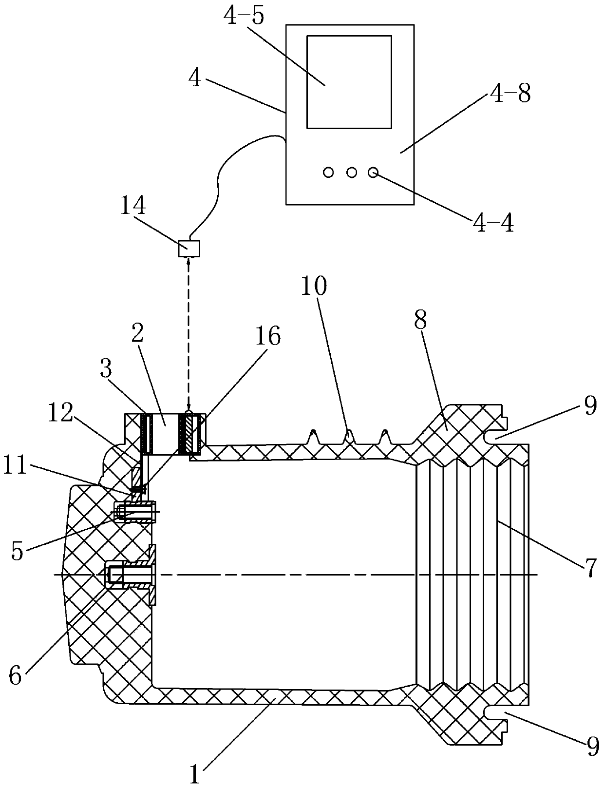
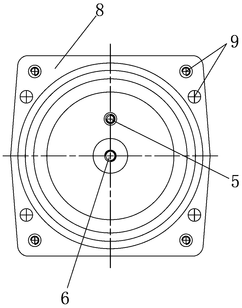
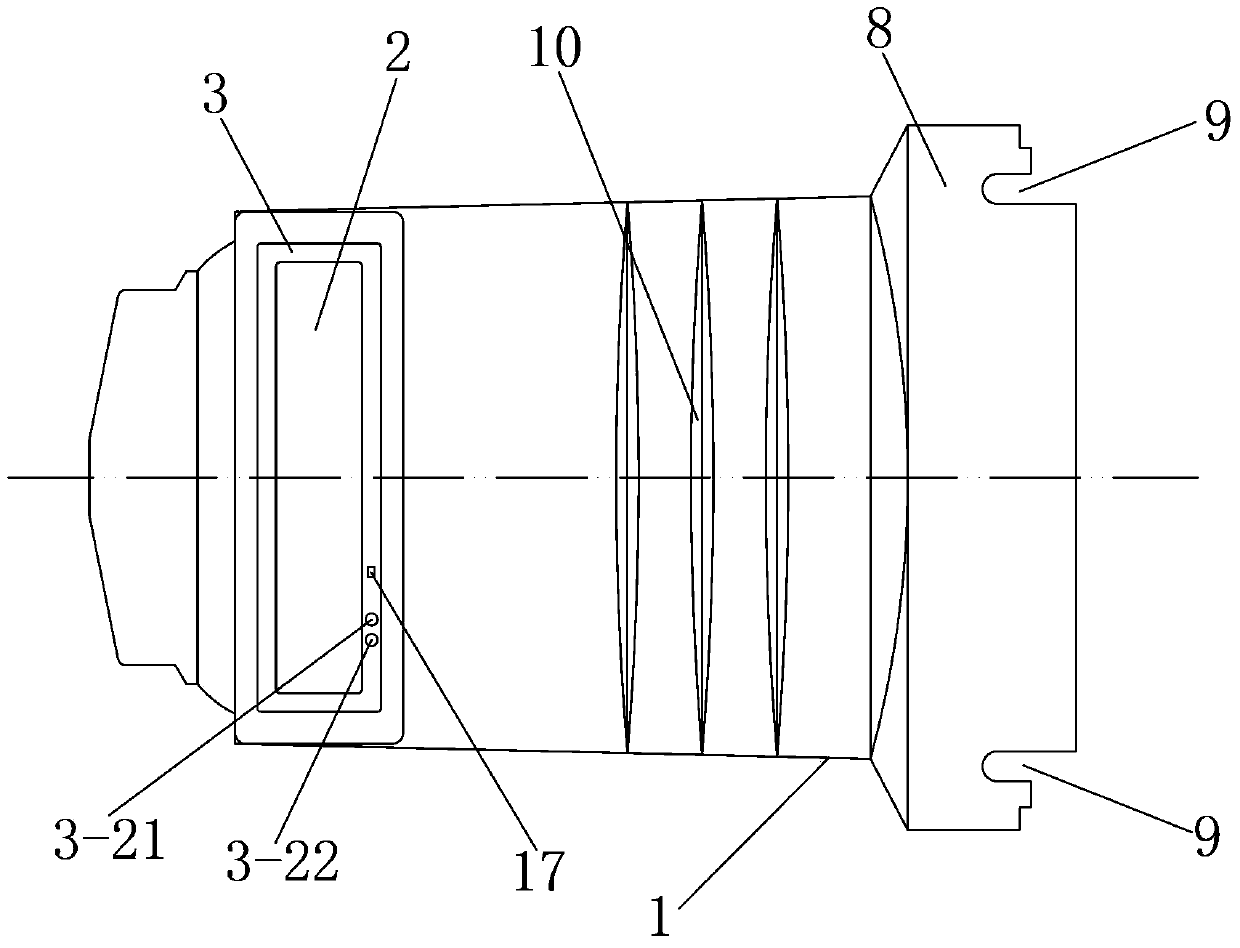
[0036] Such as figure 1 , figure 2 and image 3 As shown, the present invention includes a contact box body 1, the upper end of one side of the contact box body 1 is provided with a busbar installation hole 2, and a part of the contact box body 1 close to the busbar installation hole 2 A busbar fixing hole 5 and a static contact seat fixing hole 6 are provided on the side, and the feature is that: the inner wall of the contact box body 1 is fixedly connected with a copper gasket located on the side below the busbar installation hole 2 11. The copper gasket 11 communicates with the busbar fixing hole 5, and the copper gasket 11 is fixedly connected with a temperature detection circuit board 12, and the temperature detection circuit board 12 is provided with a fixed contact A temperature sensor 13 for real-time detection of the temperature, the busbar installation hole 2 is provided with a temperature acquisition and transmission device 3, the temperature acquisition and tra...


PUM


Abstract

The invention discloses a contact box with a built-in over-temperature protection device. The contact box comprises a contact box body; a busbar installation hole, a busbar fixing hole and a fixed contact base fixing hole are formed in the contact box body; a copper gasket is connected to the inner wall of the contact box body; a temperature detecting circuit board on which a temperature sensor is arranged is connected to the copper gasket; a temperature collecting and transmitting device is arranged in the busbar installation hole and comprises a housing, a sensing power module and a temperature collecting and transmitting circuit board, wherein the sensing power module and the temperature collecting and transmitting circuit board are arranged in the housing; a cover is connected to the housing in a clamping manner; a temperature collecting and transmitting circuit is arranged on the temperature collecting and transmitting circuit board and is connected with the temperature sensor; and the temperature collecting and transmitting circuit is in wireless connection and communication with an over-temperature protection host computer through a second wireless receiving and transmitting module. The contact box is novel and reasonable in design, can directly determine whether a fixed contact is at over-temperature, has high temperature detection accuracy, high practicability and good usage effect, and is convenient for popularization and use.

Description

technical field [0001] The invention relates to a contact box, in particular to a contact box embedded with an overheat protection device. Background technique Background technique [0002] The contact box is an insulating part commonly used in 6KV ~ 35KV high-voltage switchgear. The dynamic and static contacts installed in it during work are easily deformed or poorly contacted due to cooperation and other reasons, resulting in an increase in the temperature of the contact part, and overheating for a long time could cause a serious accident. Therefore, it is very necessary to be able to monitor the temperature of the dynamic and static contacts in the contact box at any time during the operation of the high-voltage switchgear. Some contact boxes that can monitor the temperature of the dynamic and static contacts in the contact box have also appeared in the prior art, but there are the following defects and deficiencies: 1) Some temperature sensing units are bound to the d...

Claims


Application Information

Patent Timeline
Patent Type & Authority Applications(China)
IPC IPC(8): G01K7/00G01K1/12G01K1/02G08C17/02G01K1/024
Inventor 刘权严俨
Owner 浙江江山华安电器制造有限公司
Why Eureka
Try Eureka