Current temperature on-line fault indicator and method for judging fault

A fault indicator and temperature sensor technology, used in thermometers, thermometer parts, measuring current/voltage, etc., can solve the problems of magnets burning insulating shells, accidents, and insufficient response, and achieve long-distance or wireless transmission. , saving space and cost, quick and responsive effect

Active Publication Date: 2013-10-23
ZHUHAI GENE COSMOS ELECTRIC TECH
View PDF15 Cites 16 Cited by
  • Summary
  • Abstract
  • Description
  • Claims
  • Application Information

AI Technical Summary

Problems solved by technology

Some existing power fault indication devices are often not fully functional and sensitive enough
[0003] The problems of the traditional grid line on-site monitoring equipment are: 1. Two sets of equipment are required for current monitoring and temperature monitoring, which makes the structure more complicated and increases the cost; 2. On the sensor side, the monitored value is an analog signal, and the analog The signal is directly transmitted to the host through the line. The problem is that the transmission of the analog signal is easily disturbed, and the transmission distance is limited due to the problem of attenuation; 3. The original current sensor part is just a separate current transformer, and the secondary side cannot Open circuit, once the circuit is opened, the magnetic conductor will heat up and burn the insulating shell, causing accidents, so there are potential safety hazards

Method used


Image

  • Current temperature on-line fault indicator and method for judging fault
  • Current temperature on-line fault indicator and method for judging fault
  • Current temperature on-line fault indicator and method for judging fault

Examples


Embodiment Construction

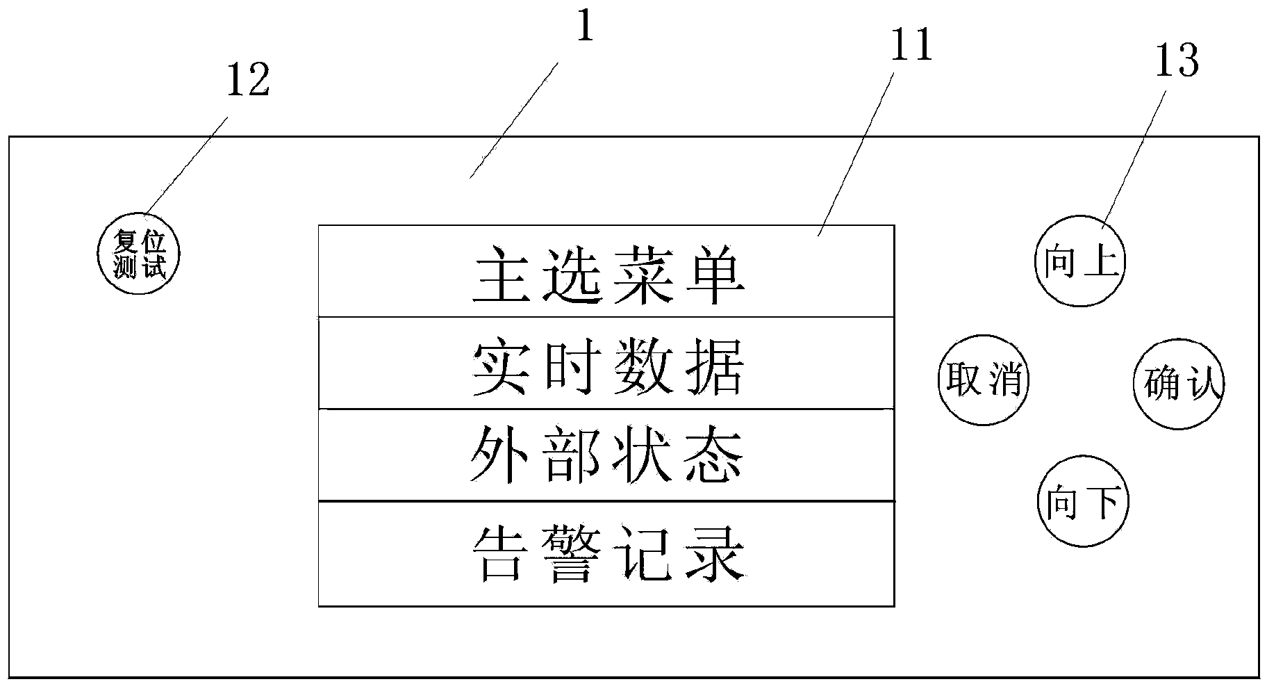
[0063] see figure 1 On the front panel of the host 1, there are a color LCD display window 11, a reset / test button 12 and a function button 13, and the signals of the phase line current and temperature sensors are transmitted to the host through cables and displayed on the color LCD display window 11. Current and temperature, the signal of the grounding current sensor is transmitted to the host through the cable and displays the current through the color LCD display window 11. The host computer includes a main chip connected with an analog-to-digital conversion module, a button control module, a voltage monitoring module, a reset circuit, a power supply circuit, a clock circuit, a liquid crystal display circuit, a signal transmission circuit and a communication circuit. The analog-to-digital conversion circuit of the main chip is used to convert the switch signal of the cable into a digital signal and send it.

[0064] The host has a function menu, which can simultaneously di...


PUM


Abstract

The invention discloses a current temperature on-line fault indicator. The current temperature on-line fault indicator comprises a main machine, three open-type phase line current and temperature sensors and an open-type grounding current sensor, a master chip is arranged in the main machine, the open-type phase line current and temperature sensors and the open-type grounding current sensor are respectively provided with an analog-to-digital conversion module, the three open-type phase line current and temperature sensors are installed on cable bodies of a three-phase cable in a clamped mode respectively, and the open-type grounding current sensor is installed on a bus of the three-phase cable in a clamped mode. The master chip is used for comparing the value of the present temperature or the present current measured by the sensors with a preset valve, and when the value reaches the preset valve, the master chip judges the alarm type, generates an alarm record and enters the alarm state. The current temperature on-line fault indicator can carry out real-time monitoring on the current and the temperature of the three-phase cable, can rapidly and accurately indicate and transmit a fault signal, and achieves the function of telecommand and the function of telemetering.

Description

technical field [0001] The invention belongs to the field of power failure indicators, and belongs to a monitoring device specially designed for automatic monitoring of power grid power supply systems. Background technique [0002] The traditional short circuit and grounding in the past only had on-site monitoring and indication of short circuit fault and ground fault, which could not display the normal working current and temperature of the cable, let alone display and query the current and temperature at the time of the fault. It brings great inconvenience to the power supply department for the maintenance and repair of the line, and the rapid analysis and solution of the fault. With the deepening of power reform, power automation management has been promoted to a new agenda. Traditional technology and management methods have been unable to adapt to new requirements. People are in urgent need of a new device, which can be used in automatic management, can monitor the pow...

Claims


Application Information

Patent Timeline
Patent Type & Authority Applications(China)
IPC IPC(8): G01R31/02G01R19/00G01K1/02G01K1/024
Inventor 肖高林徐少合
Owner ZHUHAI GENE COSMOS ELECTRIC TECH
Why Eureka
Try Eureka