
Casting method capable of preventing precise investment casting from generating hot-spot shrinkage holes

A technology for precision castings and thermal joints, applied in the fields of precision casting and casting, can solve the problems of reduced production efficiency, increased casting costs, wasted man-hours and costs, and achieved the effect of saving man-hours and costs, reducing casting costs, and improving surface quality.

Inactive Publication Date: 2013-11-20
HEBEI NORMAL UNIV
View PDF6 Cites 10 Cited by
  • Summary
  • Abstract
  • Description
  • Claims
  • Application Information

AI Technical Summary

Problems solved by technology

The disadvantage is that subsidizing metal materials not only wastes metal, but also reduces the yield of castings. In addition, removing subsidized metal materials and repairing subsidized roots wastes a lot of man-hours and costs, which reduces production efficiency and increases casting costs. Appearance quality of casting riser metal subsidy
In the prior art, there is also a discourse on substituting thermal insulation subsidy for riser metal subsidy. For example, the article "Application of thermal insulation subsidy in steel castings" on page 5 of "Machinist" thermal processing 2 published in February 1999 is exhaustive. Insulation subsidies are discussed, but this method is suitable for sand casting, because it makes the dipping operation impossible, and is not suitable for investment casting

Method used


Image

  • Casting method capable of preventing precise investment casting from generating hot-spot shrinkage holes
  • Casting method capable of preventing precise investment casting from generating hot-spot shrinkage holes
  • Casting method capable of preventing precise investment casting from generating hot-spot shrinkage holes

Examples


Embodiment

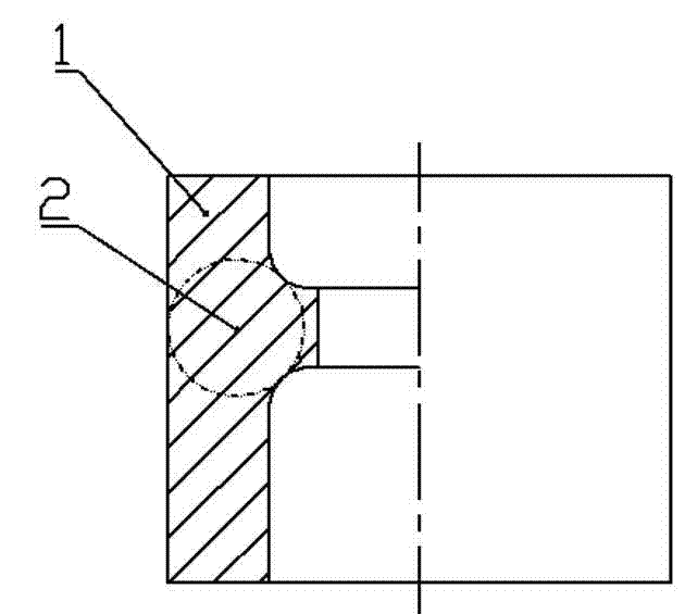
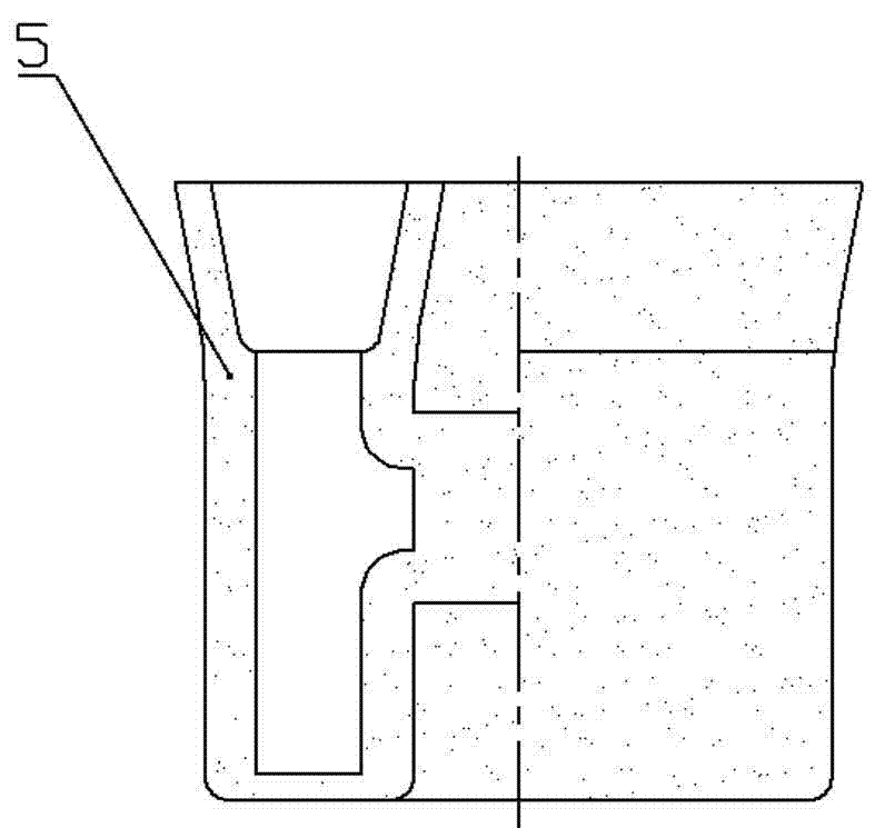
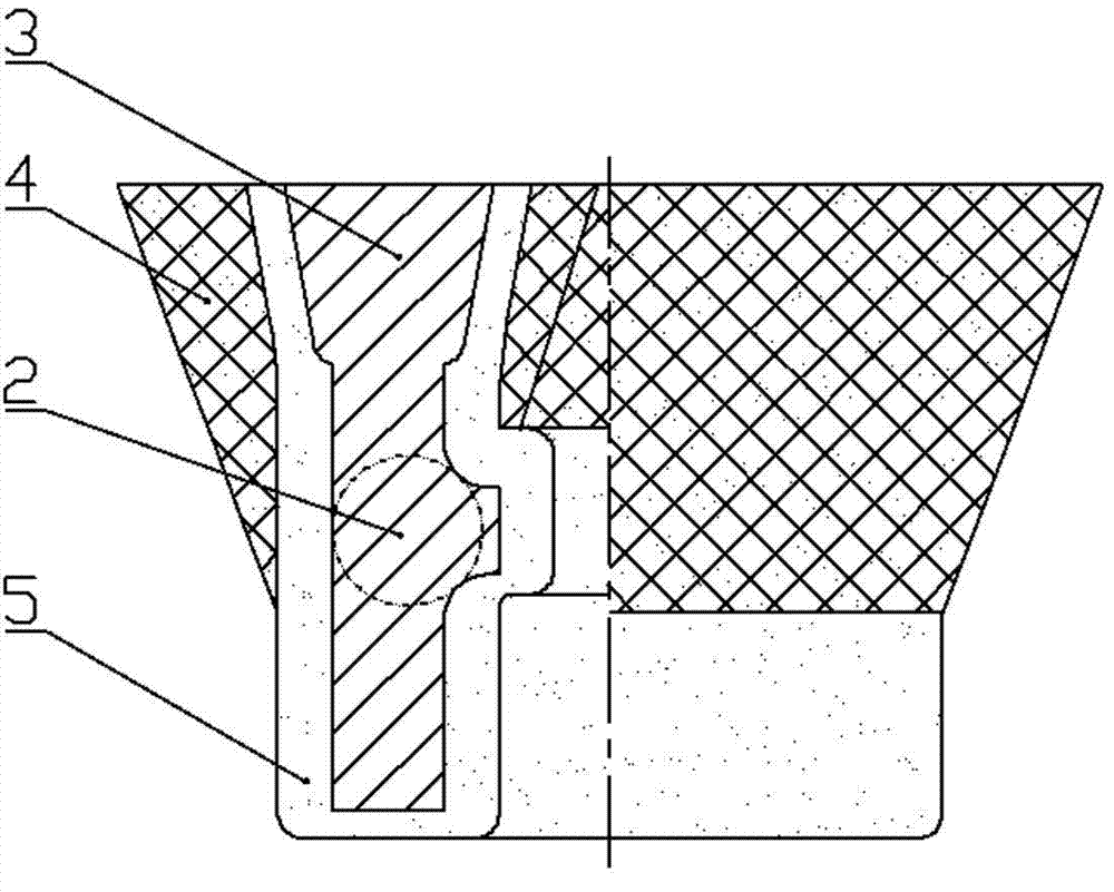
[0034] see Figure 1 to Figure 3 , a casting method for preventing thermal shrinkage cavities in investment castings, comprising the following steps:

[0035] (1) For attached figure 1 The position and height of the riser 3 are determined according to the existing technology in the casting 1 shown in the figure. The thickness of the riser root is increased by 5% to 10% compared with the wall thickness of the casting here. Mouth metal subsidy thickness.

[0036] (2) Dip, sand and dewax the same as normal parts. to obtain a shell that is approximately uniform throughout the shell thickness (see e.g. figure 2 ).

[0037] (3) Use back layer slurry: back layer powder: back layer sand = 1:1:5 mass ratio to mix mortar and mud paste. Mortar paste must be viscous, and after the shell subsidy is made, it will not creep or flow when placed.

[0038] (4) Determine the position and area of ​​the riser shell subsidy according to the conventional technology. The area of ​​the riser sh...


PUM


Abstract

The invention discloses a casting method capable of preventing a precise investment casting from generating hot-spot shrinkage holes. The casting method comprises the following steps that: a dead head position is determined according to a conventional method, and a dead head metal patch is replaced by a shell patch at a part, needing to be provided with the dead head metal patch, of the precise investment casting, wherein the material of the shell patch is mortar paste prepared from back layer slurry, back layer powder and back layer sand in a mass ratio of 1:1:5; the shell patch is bonded by the mortar paste, wherein before bonding, a layer of back layer slurry is brushed at a part needing to be bonded with the mortar paste at first, and then the wedge-shaped shell patch is formed according to a method that the thickness at a dead head is greater than that at a hot spot; after that, shell roasting and pouring are performed. Due to the action of the shell patch, the dead head and the hot spot keep a good feeding channel, thus realizing a mode of sequentially solidifying from the hot spot to the dead head, and then preventing the hot spot of the casting from generating the shrinkage holes. According to the method, patch metal for the casting is saved, the product yield of the process increases, and the visual quality of the casting is guaranteed.

Description

technical field [0001] The invention relates to a casting method, in particular to a casting method for preventing thermal shrinkage cavities of investment castings, and belongs to the technical field of precision casting. Background technique [0002] In the prior art, in order to prevent shrinkage cavities in castings, especially at hot joints far away from the riser of the casting, the riser and riser metal subsidy should be set to ensure good feeding between the riser and the fed parts. aisle. The first edition of "Sand Mold Casting Tooling Design" published by Beijing Publishing House in August 1980 pointed out the method of riser metal subsidy, and gave a reference chart of riser metal subsidy size. These methods have better solved the shrinkage cavity problem of castings. However, this method is to increase the thickness of the cavity between the hot joint and the riser of the casting. After pouring, there is an extra piece of subsidy metal material that increases t...

Claims


Application Information

Patent Timeline
IPC IPC(8): B22C9/04B22C9/08
Inventor 杜秀菊汤百智朱苏吴立勋张艳华徐岩范书果苗文丹朱九成
Owner HEBEI NORMAL UNIV
Learn More