Novel carbon fiber nanocone electrode as well as preparation method and application thereof

A carbon fiber and nanocone technology, applied in the fields of electrochemistry and material science, can solve the problems of complex technology, cumbersome operation, difficult batch preparation, etc., and achieve the effects of high temporal and spatial resolution, simplified production steps, and superior performance.

Inactive Publication Date: 2013-11-20
WUHAN UNIV
View PDF3 Cites 7 Cited by
  • Summary
  • Abstract
  • Description
  • Claims
  • Application Information

AI Technical Summary

Problems solved by technology

However, this method is complex in technology, difficult to operate, and the electrode repeatability is not good.
So far, various methods such as chemical and flame etching have been used to fabricate needle-shaped carbon fiber nanoelectrodes, but it is very difficult to insulate the active surface of the electrode and expose the extremely small nanotips.
Although it has been reported in the literature that a variety of methods are used to expose nan

Method used


Image

  • Novel carbon fiber nanocone electrode as well as preparation method and application thereof
  • Novel carbon fiber nanocone electrode as well as preparation method and application thereof
  • Novel carbon fiber nanocone electrode as well as preparation method and application thereof

Examples


Embodiment 1

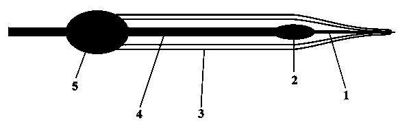
[0034] A new type of carbon fiber nanocone electrode, the schematic diagram of its structure is shown in figure 1 As shown, it includes carbon fiber 1, electrode lead 4 and glass capillary 3; carbon fiber 1 and electrode lead 4 are connected by conductive glue 2, and the front part of carbon fiber 1 is etched into a needle shape at 50-100 μm, and the diameter of the needle-shaped tip is 100-100 μm. 300nm; one end of the glass capillary 3 is drawn into a tip with a diameter less than or equal to 1 μm; the carbon fiber 1 connected to the electrode lead 4 penetrates the pointed glass capillary 3, and the carbon fiber 1 exposes the tip of the glass capillary 3, and the electrode lead 4 exposes the glass capillary 3, this end is sealed with AB glue 5.

[0035] The carbon fiber 1 has a diameter of 5-7 μm and a length of 2-3 cm; the electrode lead 4 is a copper wire with a diameter of 0.3-0.5 mm and a length of 8-12 cm; the conductive glue 2 is graphite Conductive glue (ie epoxy res...

Embodiment 2

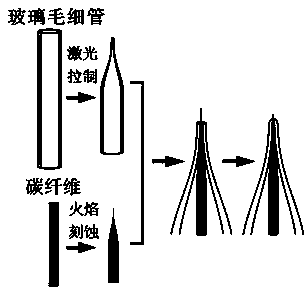
[0038] (1) Glue the carbon fiber (Goodfellow Co., Oxford, U.K.) with a diameter of 7 μm and a length of 2 to 3 cm to the electrode lead copper wire (0.4 mm in diameter and about 10 cm in length) with graphite conductive adhesive, and place it at room temperature until the conductive adhesive solidifies; The carbon fibers were ultrasonically cleaned with acetone, ethanol, and double distilled water in sequence, and dried in air.

[0039] (2) Put the carbon fiber close to the oxygen-enriched blue flame of the alcohol lamp, and immediately withdraw from the flame when the tip of the carbon fiber is slightly red, and etch the 50-100 μm of the front part of the carbon fiber into a needle shape, and the tip diameter is 100-300nm.

[0040] (3) Pull a clean glass capillary (length 10cm, outer diameter 1.0mm, inner diameter 0.58mm) into a tip with a diameter of about 1 μm (specific parameters are heat=380 ,fil=4,vel=40,del=200,pul=0).

[0041] (4) Insert the carbon fiber connected wit...

Embodiment 3

[0045] (1) Bond the carbon fiber (Goodfellow Co., Oxford, U.K.) with a diameter of 7 μm and a length of 2 to 3 cm to the electrode lead copper wire (0.35 mm in diameter and about 10 cm in length) with graphite conductive adhesive, and place it at room temperature until the conductive adhesive solidifies; Then the carbon fibers were ultrasonically cleaned with acetone, ethanol, and twice distilled water in sequence, and dried in the air.

[0046] (2) Put the carbon fiber close to the oxygen-enriched blue flame of the alcohol lamp, and immediately withdraw from the flame when the tip of the carbon fiber is slightly red, and etch the 50-100 μm of the front part of the carbon fiber into a needle shape, and the tip diameter is 100-300nm.

[0047] (3) Pull a clean glass capillary (length 10cm, outer diameter 1.0mm, inner diameter 0.50mm) into a tip with a diameter of about 1 μm (the specific parameters are heat = 390, fil=5, vel=40, del=200, pul=0).

[0048] (4) Insert the carbon f...


PUM

PropertyMeasurementUnit
Diameteraaaaaaaaaa
Diameteraaaaaaaaaa
Lengthaaaaaaaaaa

Abstract

The invention discloses a novel carbon fiber nanocone electrode as well as a preparation method and application thereof, belonging to the field of electrochemistry and material science. The novel carbon fiber nanocone electrode comprises a carbon fiber, an electrode lead and a glass capillary tube, wherein the carbon fiber is connected with the electrode lead through a conductive adhesive; the front part, as long as 50-100 microns, of the carbon fiber is etched to be of a needle shape, and the tip end of the needle-shaped part has the diameter of 100nm-300nm; one end of the glass capillary tube is pulled to form a tip end with the diameter less than or equal to 1micron; the carbon fiber connected with the electrode lead penetrates into the pulled tip of the glass capillary tube, and is exposed out of the tip end of the glass capillary tube; the electrode lead is exposed out of the other end of the glass capillary tube, and the end is sealed by an AB adhesive. According to the invention, the problem that after a nano electrode is insulated, the tip end cannot be exposed easily is solved radically. The carbon fiber nanocone electrode provided by the invention has the advantages of low noise, high sensitivity and high temporal-spatial resolution, and can be applied to real-time detection on neurotransmitter in synaptic cleft in neuroscience research.

Description

technical field [0001] The invention belongs to the field of electrochemistry and material science, and relates to a novel carbon fiber nano-cone electrode and its preparation method and application. Background technique [0002] The current methods for constructing nanoelectrodes are generally divided into one-step method and two-step method. The one-step method is to insulate the part other than the tip of the electrode, mainly to pass the etched metal wire through or dip the molten insulating material such as paraffin, glass and other insulating materials. Due to the thick insulating layer, although the prepared nanoelectrode has a small active surface, its geometric size is large, which limits the application of the electrode in the nanoscale range. The two-step method first fully insulates the electrode, and then removes the insulation from the electrode tip by various methods. However, this method is complicated in technology, difficult in operation and poor in repea...

Claims


Application Information

Patent Timeline
IPC IPC(8): G01N27/30
Inventor 黄卫华李玉桃吴文展张淑慧
Owner WUHAN UNIV
Why Eureka
Try Eureka