Inverter power system

A technology of inverter power supply and circuit, which is applied in the direction of control/regulation system, electrical components, and adjustment of electrical variables, etc., can solve the problems of large frequency variation range, wide variation range of PWM converter duty cycle, and low conversion efficiency, and achieve The effect of improving conversion efficiency and prolonging effective use time

Active Publication Date: 2015-11-25
HUAWEI DIGITAL POWER TECH CO LTD
View PDF4 Cites 0 Cited by
  • Summary
  • Abstract
  • Description
  • Claims
  • Application Information

AI Technical Summary

Problems solved by technology

[0006] In a 48V battery system, the charging and discharging voltage range of the battery is usually between 36V-60V, and the effective value of the inverter output is 230V sinusoidal AC, so at least the voltage at both ends of the bus capacitor is 230V×1.414=325.22V, and the voltage at both ends of the bus capacitor is 230V×1.414=325.22V. The highest voltage generally does not exceed 425V, so the DC / DC isolation converter input voltage (36V-60V, high and low voltage ratio 1.67) is relatively wide compared to its output voltage (325V-425V, high and low voltage ratio 1.3), which is not conducive to DC / DC In the design of the converter, if a Pulse Width Modulation (PWM) converter is selected, the duty cycle needs to be changed to meet the wide range of input and output voltage requirements. For example, when the battery voltage is 60V, the duty cycle needs to be reduced to ensure The output voltage of the DC / DC isolation converter is lower than 425V. When the battery voltage is 36V, the duty cycle needs to be increased to ensure that the output voltage of the DC / DC isolation converter is higher than 325V, resulting in the duty cycle of the PWM converter. large, low conversion efficiency
Similarly, if an ordinary resonant converter is used, the resonant frequency needs to be changed to meet the wide range of input and output voltage requirements, but the frequency range is large, the device stress is high, and the conversion efficiency is also difficult to guarantee

Method used


Image

  • Inverter power system
  • Inverter power system
  • Inverter power system

Examples


Embodiment Construction

[0028] In order to make the object, technical solution and advantages of the present invention clearer, the present invention will be further described in detail below in conjunction with the accompanying drawings. Obviously, the described embodiments are only some embodiments of the present invention, rather than all embodiments . Based on the embodiments of the present invention, all other embodiments obtained by persons of ordinary skill in the art without making creative efforts belong to the protection scope of the present invention.

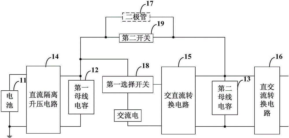
[0029] figure 1 A structural block diagram of an inverter power supply system provided for an embodiment of the present invention. In this embodiment, the inverter power supply system includes: a battery 11 , a first bus capacitor 12 , a second bus capacitor 13 , a DC isolation boost circuit 14 , an AC-DC conversion circuit 15 and a DC-AC conversion circuit 16 .

[0030] Wherein, the second bus capacitor 13 is connected to the first bus c...


PUM


Abstract

The invention provides an inversion power supply system. A first bus capacitor is connected with an ac-dc converting circuit via a first selector switch when a dc bus voltage of the first bus capacitor cannot satisfy inversion output requirement of the ac-dc converting circuit, and the dc bus voltage of the first bus capacitor is secondarily boosted via the ac-dc converting circuit, thereby broadening the range of output voltage of a second bus capacitor, satisfying the inversion output requirement of the ac-dc converting circuit, ensuring wide voltage input of a battery, satisfying wide input / output voltage range of the inversion power supply system, and prolonging effective service life of the battery. The ac-dc converting circuit is used to boost the dc bus voltage of the first bus capacitor, thereby solving the problem that conversion efficiency is low due to the fact that in the prior art, the wide input / output voltage range of the inversion power supply system is satisfied by changing the duty ratio of a PWM converter or the resonant frequency of a resonant converter.

Description

technical field [0001] The invention relates to power supply technology, in particular to an inverter power supply system. Background technique [0002] Inverter power systems are widely used in various occasions that require reliable power supply. For example, in the field of communication, uninterruptible power supplies such as inverters or UPS (Uninterruptible Power System) are usually used to supply power to key AC loads. [0003] The inverter power supply usually has 3 power ports: DC (battery) input port, AC input port and AC output port, corresponding to 3 power converters, namely: DC / DC boost conversion for raising the low voltage of the battery to the high voltage of the bus capacitor Converter, AC-DCPFC converter that converts mains AC into high voltage of bus capacitor and completes input power factor correction, DC-AC inverter that converts high voltage of DC bus capacitor into alternating current (AC) output. [0004] Under the normal condition of the AC mains ...

Claims


Application Information

Patent Timeline
Patent Type & Authority Patents(China)
IPC IPC(8): H02M7/54H02M3/337H02M7/5387
CPCY02B70/1433Y02B70/1441Y02B70/10
Inventor 潘灯海张学黄伯宁
Owner HUAWEI DIGITAL POWER TECH CO LTD
Why Eureka
Try Eureka