Static flow guide branch pipe dosing type pipeline dosing mixer

A pipeline dosing and mixer technology, which is applied in the directions of fluid mixers, mixers, chemical instruments and methods, etc., can solve the problems of high dosing operation cost, uneven mixing effect, increased energy consumption, etc., and reduce the dosing operation. The effect of cost, saving drug consumption, low maintenance cost

Inactive Publication Date: 2013-11-27
TIANJIN HUASHUI WATER CONSTR
View PDF4 Cites 6 Cited by
  • Summary
  • Abstract
  • Description
  • Claims
  • Application Information

AI Technical Summary

Problems solved by technology

The existing dosing method adopts directly putting the medicine into the water flow of the pipeline through the dosing tube, and its disadvantages are: 1. The medicine flows in the same direction as the raw water in the pipeline, the contact area is small, the mixing is insufficient, and the mixing effect is uneven. The drug is hydrolyzed before it fully takes effect, the drug utilization rate is low, and the mass transfer efficiency is low
2. In the parts or working conditions where the dosing effect is extremely poor, it is necessary to increase the mechanical agitation to improve the use effect of the medicine, increase the energy consumption and increase the cost of the dosing operation
Therefore, the use of existing dosing facilities and dosing methods directly affects the effect of impurity removal, resulting in poor precipitation, poor effluent quality, waste of medicines, and waste of energy. The quality of effluent water cannot be fully and flexibly controlled through the dosing link.

Method used


Image

  • Static flow guide branch pipe dosing type pipeline dosing mixer
  • Static flow guide branch pipe dosing type pipeline dosing mixer
  • Static flow guide branch pipe dosing type pipeline dosing mixer

Examples


Embodiment Construction

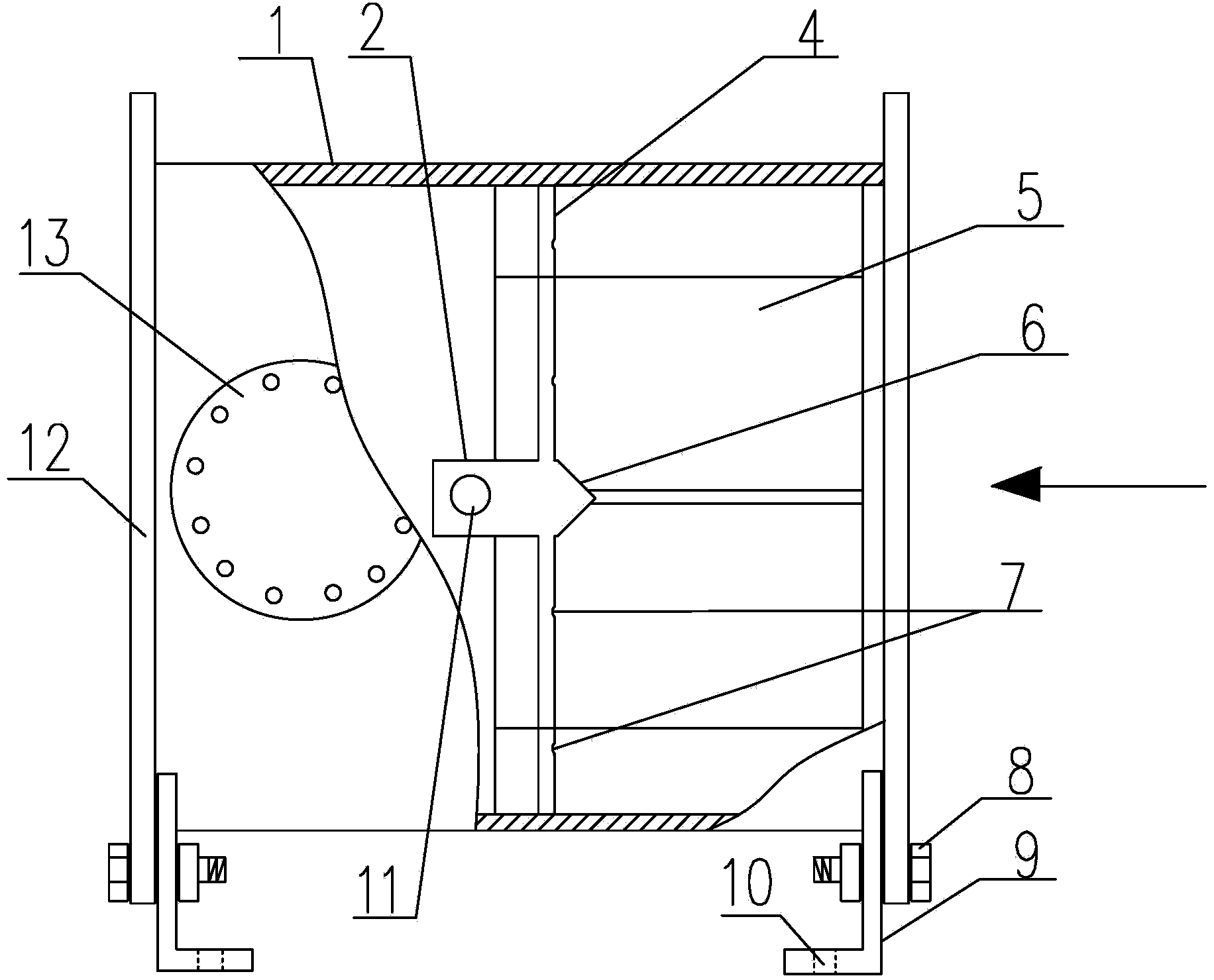
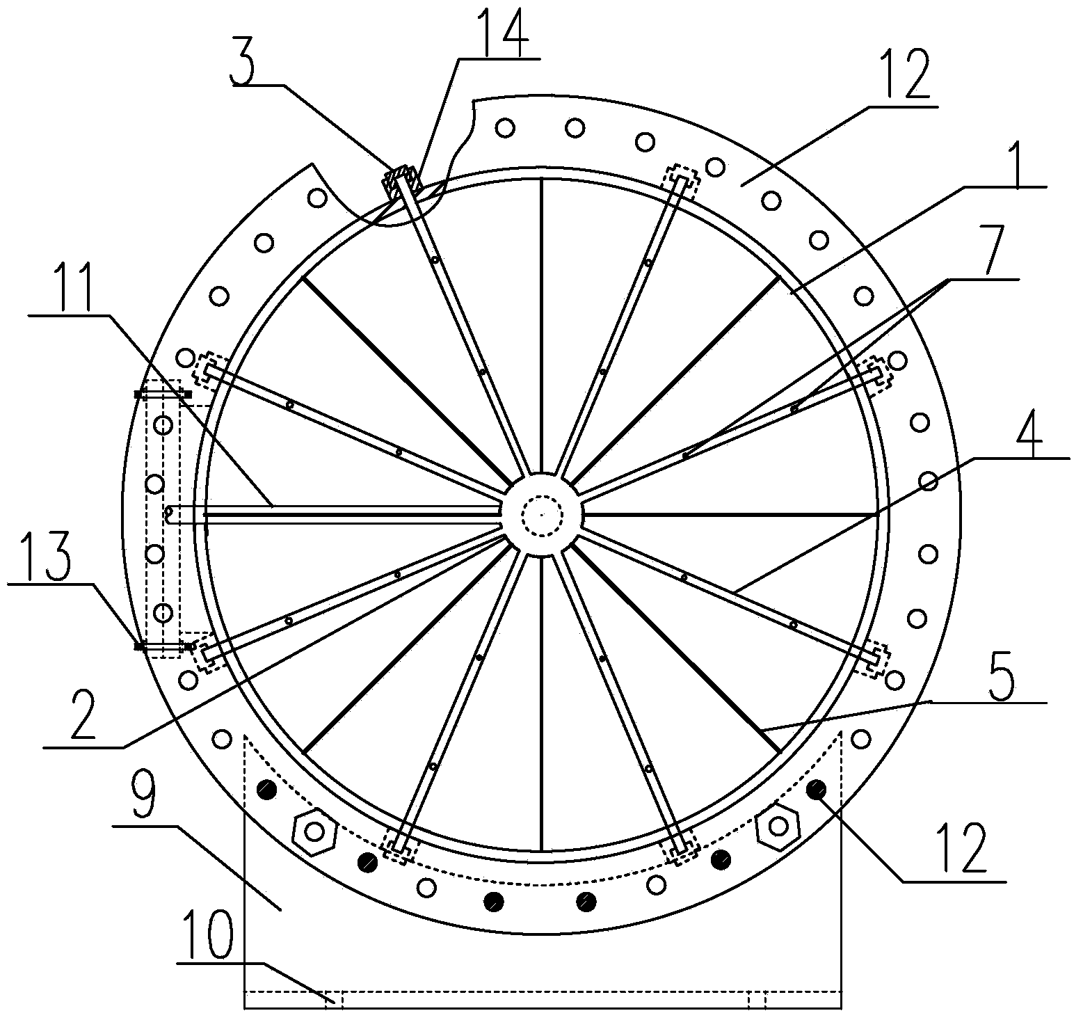
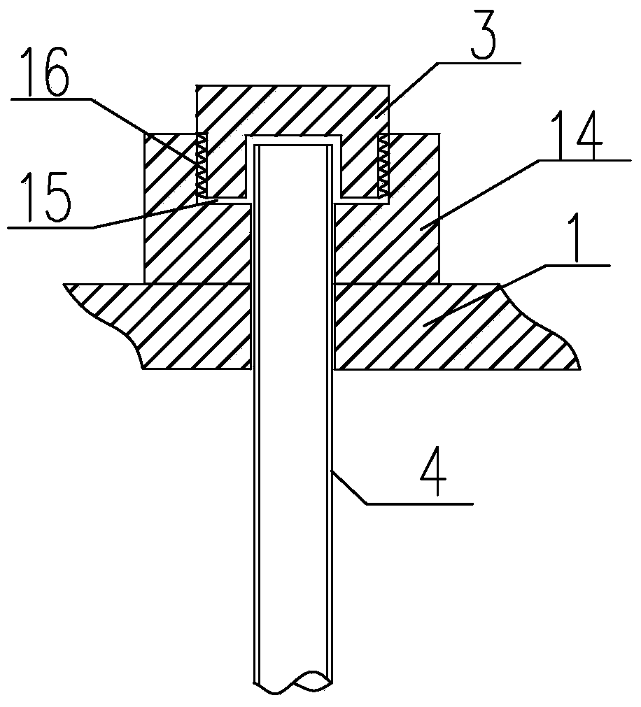
[0017] Figure 1 ~ Figure 3 It shows a static diversion type branch pipe dosing type pipeline dosing mixer, which is characterized in that it includes a cylindrical pipe body 1 connected in the fluid pipeline through flanges 12 at both ends, and at the center of the pipe body 1 A cylindrical dosing central distribution chamber 2 is provided on the same center line as the pipe body, and the outer wall surrounding the dosing central distribution chamber 2 is fixedly arranged between it and the inner wall of the pipe body 1 and radiates along the radial direction of the pipe body. A plurality of guide vanes 5 uniformly distributed in a radial shape and a plurality of dosing branch pipes 4 provided with a drug outlet hole 7 communicated with the distribution chamber 2 of the dosing center on the same plane that are also uniformly distributed radially, the guide vanes 5 extends axially along the pipe body to the water-facing port of the pipe body 1. The dispensing room of the dosi...


PUM

PropertyMeasurementUnit
diameteraaaaaaaaaa

Abstract

The invention relates to a static flow guide branch pipe dosing type pipeline dosing mixer, which is characterized by comprising a cylindrical pipe body connected in a fluid pipeline through a flange, wherein a cylindrical dosing center distribution chamber is arranged at the central position of the pipe body in a manner of sharing the central line with the pipe body, a plurality of flow guide blades and a plurality of dosing branch pipes are fixedly arranged between the outer wall of the dosing center distribution chamber and the inner wall of the pipe body, the plurality of flow guide blades are uniformly and radially arranged along the radial direction of the pipe body, the plurality of dosing branch pipes are located on the same plane, communicated with the dosing center distribution chamber and provided with medicine discharge holes, and the flow guide blades are extended to the water facing side port of the pipe body along the axial direction; the dosing center distribution chamber is connected with a total medicine supply pipe communicated with a medicine source; the water facing end face of the dosing center distribution chamber is a convex conical surface; a sealing cover is covered at the pipe orifices of the dosing branch pipes; a support is arranged on the pipe body. The static flow guide branch pipe dosing type pipeline dosing mixer provided by the invention has the advantages of ensuring uniform medicine mixing, improving the mass transfer efficiency, guaranteeing the water discharge quality, improving the medicine utilization rate and reducing the energy consumption.

Description

technical field [0001] The invention mainly relates to a dosing mixer for adding coagulant and coagulant aid to water supply and drainage pipelines in urban life and industrial water supply treatment and sewage treatment, especially to a static diversion type branch pipe dosing type pipeline dosing mixer. Medicine mixer. Background technique [0002] At present, the function of adding coagulants and coagulants to the water supply and drainage pipes in urban water purification plants, sewage treatment plants, and sewage treatment is to precipitate and filter impurities in the fluid, improve the quality of effluent or drainage water, and reduce turbidity , so that the fluid in the pipeline meets the national drinking water or discharge water quality requirements. The existing dosing method adopts directly putting the medicine into the water flow of the pipeline through the dosing tube, and its disadvantages are: 1. The medicine flows in the same direction as the raw water in ...

Claims


Application Information

Patent Timeline
Patent Type & Authority Applications(China)
IPC IPC(8): B01F5/00B01F15/02C02F1/00
Inventor 贾涛王君郑鑫杨海
Owner TIANJIN HUASHUI WATER CONSTR
Why Eureka
Try Eureka