High-capacity compressed air energy storage efficient power generating system

A technology of compressed air energy storage and compressed air, which is applied in the field of high-capacity compressed air energy storage and high-efficiency power generation systems, can solve the problems of insufficient peak regulation capacity, small capacity, and unenvironmental protection, achieve high secondary frequency regulation capacity, and increase power generation. The effect of capacity

Inactive Publication Date: 2013-11-27
NORTH CHINA ELECTRIC POWER UNIV (BAODING)
View PDF7 Cites 35 Cited by
  • Summary
  • Abstract
  • Description
  • Claims
  • Application Information

AI Technical Summary

Problems solved by technology

Although my country's electric power industry has made considerable progress, there are still many problems: the peak-to-valley difference in power grid load increases year by year, and the peak-shaving capacity is insufficient; the total power demand is large, the energy structure is unreasonable, and the proportion of clean energy power generation is not high; because There are various obstacles, and the power generation of many renewable energy power plants cannot be connected to the grid, resulting in the emergence of large-scale "abandoned wind" and "abandoned solar energy", resulting in a great waste of renewable energy and renewable energy investment; The proportion of power ...

Method used


Image

  • High-capacity compressed air energy storage efficient power generating system

Examples


Embodiment Construction

[0020] The present invention provides a large-capacity compressed air energy storage and high-efficiency power generation system. The present invention will be further described below with reference to the drawings and specific embodiments.

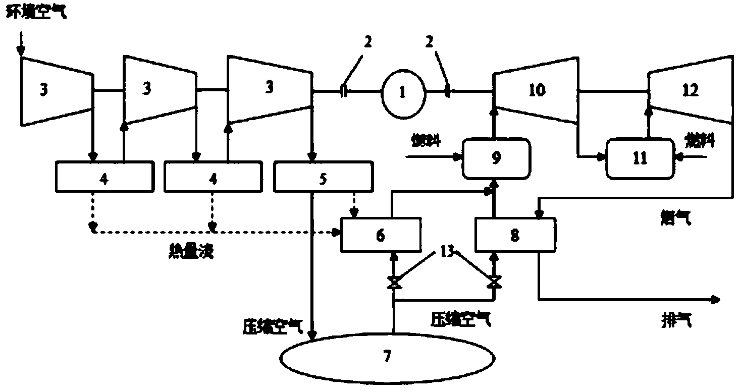
[0021] The large-capacity compressed air energy storage and high-efficiency power generation system has a structure such as figure 1 As shown, it consists of a compressed air energy storage subsystem and a compressed air energy discharging power generation subsystem.

[0022] The generator motor 1 is coaxially connected with the multi-stage compressor 3 through the clutch 2. The compressors 3 of each stage are connected to the indirect cooler 4, the last stage compressor is connected to the cooler 5, and the air pipe of the cooler 5 is connected to the air storage chamber. 7 is connected, the heat flow pipes of the indirect cooler 4 and the cooler 5 are connected to the heat flow side of the heat accumulator 6 to form a compressed air energy s...


PUM


Abstract

The invention belongs to the field of high-capacity industrial energy storage, and particularly relates to a high-capacity compressed air energy storage efficient power generating system. A power generating electromotor is respectively connected with a plurality of air compressors as well as a high-pressure turbine and a low-medium-pressure turbine coaxially through clutches; intercoolers are connected among the air compressors; the last air compressor is connected with a cooler; an air pipeline of the cooler is connected with an air storage chamber; the intercoolers and a hot flow pipeline of the cooler are connected with the hot flow side of a heat storage device; the air storage chamber is respectively connected with the inlets of the air sides of the heat storage device and a heat regenerator; the air sides of the heat storage device and the heat regenerator are sequentially connected with a combustor and the high-pressure turbine; a regenerator is connected between the high-pressure turbine and the low-medium-pressure turbine; the outlet of the low-medium-pressure turbine is connected with the smoke side of the heat regenerator. The system can absorb unstable power load generated by renewable energy sources on a large scale, also can absorb the residual electric power when the power grid load is at a low ebb, and releases the stored energy at the electricity consumption peak so as to meet the requirement of the power grid pitch peak.

Description

Technical field [0001] The invention belongs to the field of large-capacity industrial energy storage, and particularly relates to a large-capacity compressed air energy storage high-efficiency power generation system for energy cascade utilization. Background technique [0002] As my country's economy continues to grow, China's energy industry has developed rapidly, and an energy supply pattern with coal as the mainstay, electricity as the center, and the comprehensive development of oil, natural gas and renewable energy has been initially formed. It is expected that my country's energy demand will maintain a strong growth trend for a long time to come. Although China's power industry has made considerable progress, there are still many problems: grid load peak-to-valley difference is increasing year by year, peak shaving capacity is insufficient; the total power demand is large, the energy structure is unreasonable, and the proportion of clean energy power generation is not hig...

Claims


Application Information

Patent Timeline
IPC IPC(8): F02C6/16F02C7/08F04D25/08F04D25/16F04D29/58F01D15/10
CPCY02E60/15Y02E70/30Y02E50/12Y02E50/10Y02E60/16
Inventor 付忠广卢可
Owner NORTH CHINA ELECTRIC POWER UNIV (BAODING)
Why Eureka
Try Eureka