Supercharge Your Innovation With Domain-Expert AI Agents!

Hydraulic double-pump confluence control device and all-terrain crane

A double-pump confluence and control device technology, which is applied to cranes, fluid pressure actuators, mechanical equipment, etc., can solve problems such as low reliability, poor interchangeability, and bulkiness, and achieve small spool diameters and reduced flow rates , the effect of less power consumption

Active Publication Date: 2013-11-27
XUZHOU HEAVY MASCH CO LTD
View PDF5 Cites 3 Cited by
  • Summary
  • Abstract
  • Description
  • Claims
  • Application Information

AI Technical Summary

Problems solved by technology

In this way, the entire valve block needs to be larger, which is a bit cumbersome, and if the electromagnet is large, the control power will be large, and the power consumption of the vehicle power supply will be large.
[0007] 2) The reliability is not high: With the development of hydraulic technology today, with the increase of the flow rate, the diameter of the spool increases, and the force to push the spool also increases. The traditional solenoid valve control has become difficult, and the spool The control form is gradually changed from pure electric electromagnet control to hydraulic control form (the hydraulic pilot oil is used to push the spool, and the electric only controls the switch and size of the pilot oil)
Due to the use of large electromagnet control, electromagnet control is difficult, so the reliability of the entire control is not high
[0008] 3) Interchangeability is not strong: Considering the requirements of confluence on two-position three-way electromagnetic reversing valve, this valve needs to adopt cartridge type or plate type valve
However, valves with this function are rarely used. When a fault occurs and need to be replaced, this type of valve with less application must be selected, and the interchangeability is poor.

Method used


Image

  • Hydraulic double-pump confluence control device and all-terrain crane
  • Hydraulic double-pump confluence control device and all-terrain crane
  • Hydraulic double-pump confluence control device and all-terrain crane

Examples


Embodiment Construction

[0025] The technical solution of the present invention will be described in further detail below with reference to the drawings and embodiments.

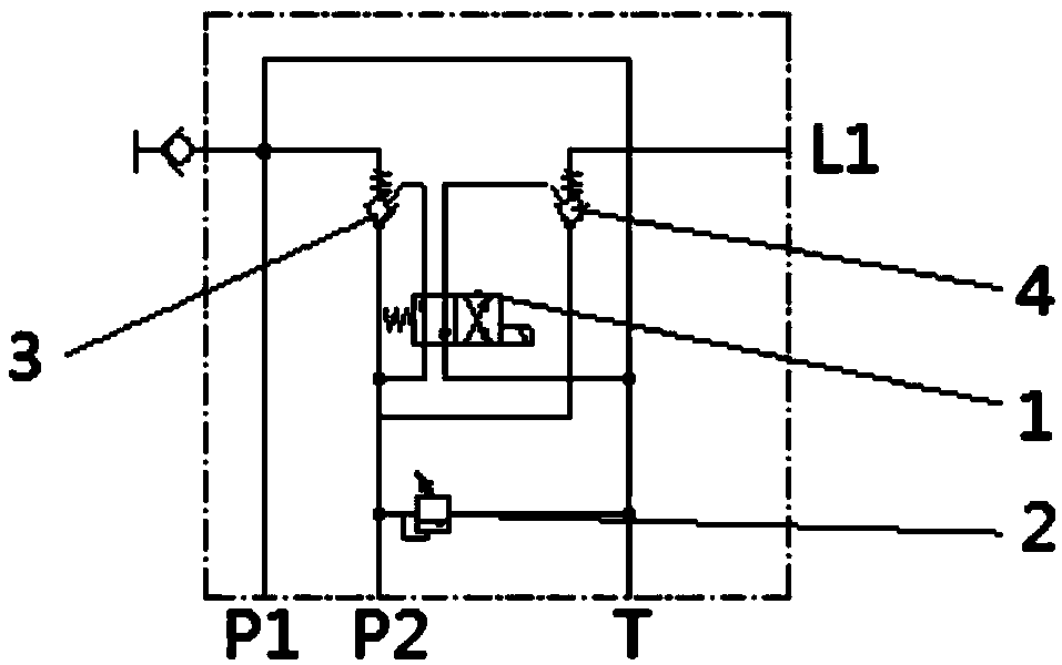
[0026] Such as figure 1 As shown, it is a schematic diagram of the hydraulic principle of an embodiment of the hydraulic double-pump confluence control device of the present invention. In this embodiment, the hydraulic dual-pump confluence control device includes a confluence solenoid valve 1 , a main overflow valve 2 , a first pilot-closed hydraulic control check valve 3 and a second pilot-close hydraulic control check valve 4 . These valve parts can be arranged in the same valve block, or can be arranged in a combined valve block etc. as required.

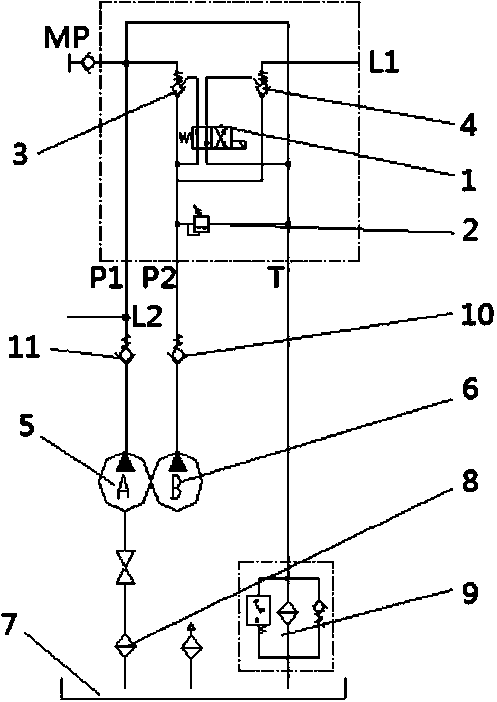
[0027] The oil inlet and oil outlet of the main relief valve 2 respectively pass through figure 1 The P2 oil port and the T oil port on the middle valve block communicate with the second oil pump B with a relatively small flow rate and the oil tank T, and are mainly used to control t...


PUM


Abstract

The invention relates to a hydraulic double-pump confluence control device and an all-terrain crane. The hydraulic double-pump confluence control device comprises a confluence solenoid valve, a main overflow valve and an interlocking structure, an oil inlet and an oil outlet of the main overflow valve are communicated with a second oil pump and an oil tank respectively, the interlocking structure is composed of two closed pilot operated check valves, and confluence switching is performed by the confluence solenoid valve. According to the hydraulic double-pump confluence control device, the interlocking confluence control mode that the closed pilot operated check valves and the confluence solenoid valve are combined for control is adopted, during confluence of oil pumps, and oil output by the second oil pump is directly connected to a confluence point connected with a first oil pump in an out-of-valve confluence mode rather than through the confluence solenoid valve in existing hydraulic confluence control systems, so that the confluence solenoid valve only serves as a channel for controlling the oil. Compared with existing hydraulic confluence control systems, the hydraulic double-pump confluence control device has the advantages that the flow of the confluence solenoid valve can be reduced, the spool diameter of the confluence solenoid valve can be reduced, the size of an electromagnet can be reduced, the power consumption is low, and the reliability is high.

Description

technical field [0001] The invention relates to the field of engineering machinery, in particular to a hydraulic double-pump confluence control device and an all-terrain crane. Background technique [0002] The outrigger hydraulic system of the crane chassis often uses an oil pump to realize the control purpose of the horizontal oil cylinder and the vertical oil cylinder. Practice has proved that this application is feasible, simple and reliable. However, with the gradual increase of the tonnage of all-terrain cranes, the use of traditional H-shaped outriggers requires higher and higher frame strength. Therefore, super-large tonnage cranes widely use radial outriggers that do not require high frame strength. Legs, this kind of outrigger form, in addition to the need for horizontal and vertical oil cylinders, the outriggers need to be put out first when working, so the swing oil cylinder is added, and the movable outriggers need to be disassembled due to the weight limit of t...

Claims


Application Information

Patent Timeline
IPC IPC(8): F15B13/02B66C23/80
Inventor 宋建军曹培雷张永亮陶巍巍
Owner XUZHOU HEAVY MASCH CO LTD
Features
  • R&D
  • Intellectual Property
  • Life Sciences
  • Materials
  • Tech Scout
  • Unparalleled Data Quality
  • Higher Quality Content
  • 60% Fewer Hallucinations
Learn More