Weak X-ray 3D (three-dimensional) imaging method

An imaging method and 3D technology, applied in the direction of using radiation for material analysis, can solve problems such as low resolution, and achieve the effect of wide application fields, speed improvement, and efficiency improvement

Inactive Publication Date: 2013-11-27
BEIJING UNIV OF CHEM TECH
View PDF4 Cites 2 Cited by
  • Summary
  • Abstract
  • Description
  • Claims
  • Application Information

AI Technical Summary

Problems solved by technology

At the same time, when selecting the detection system and control system, whether it is the mode of the scanning system or the selection of the model of the AD simulator, the speed of operation can be effectively improved, and the problem of low resolution of weak X-ray industrial CT technology can be solved from the perspective of system rapidity. question

Method used


Image

  • Weak X-ray 3D (three-dimensional) imaging method
  • Weak X-ray 3D (three-dimensional) imaging method
  • Weak X-ray 3D (three-dimensional) imaging method

Examples


Embodiment 1

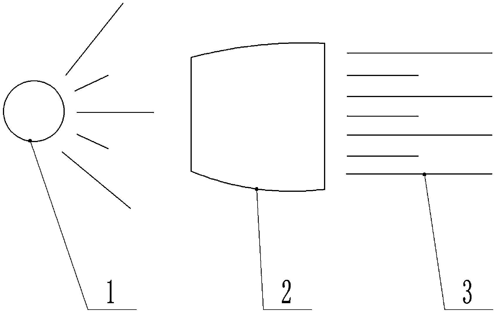
[0036] Embodiment 1: The working principle of the lens module is as follows figure 2 shown. The module is mainly composed of weak X-ray point light source 1, X-ray lens device 2 and parallel X-ray 3. Wherein the energy of the X-ray point light source 1 is below 100KeV, which is a weak X-ray. The X-ray lens device 2 is composed of a parallel-beam X-ray lens with a semi-lens structure. Its function is to convert the scattered X-rays into parallel-beam X-rays. When the weak X-ray from the X-ray point source 1 enters the X-ray lens device , the weak X-ray propagates inside the lens, part of it is absorbed by the lens wall, and the remaining part is transmitted in parallel by the inner track of the lens to form parallel X-ray 3 .

Embodiment 2

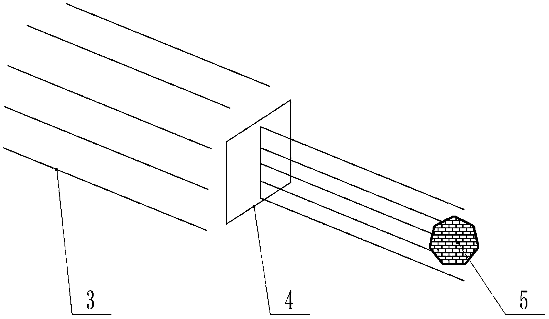
[0037] Embodiment 2: The working principle of the measured object module is as follows image 3 shown. The module is mainly composed of parallel X-rays 3 , long slit lead plates 4 and objects to be measured 5 . The parallel X-ray 3 that comes out from embodiment one enters in the long slit lead plate 4, and the lead material can shield X-ray, and there is a slit in the middle of the long slit lead plate 4, and the width between the slits is greater than the X-ray wavelength. It can ensure that X-rays can be converted into line light sources without diffraction. The X-ray passes through the slit to form a line X-ray, which penetrates the object to be measured 5 and is received by the detection array module to form a line X-ray source 6 containing tomographic image information. In the case where the length of the slit is long enough, the object to be measured 5 can scan the entire object only by parallel movement of the workbench where the object to be measured 5 is located du...

Embodiment 3

[0038] Embodiment 3: The working principle of the detector array module is as follows Figure 4 shown. The module is mainly composed of an X-ray light source 6 , a scintillator 7 and a photodiode 8 . The X-ray light source 6 enters the scintillator 7 to excite the atoms or molecules, and the excited atoms or molecules emit light during the de-excitation process, and convert the X-rays with a very short wavelength into fluorescence. The fluorescence has a long wavelength, so it is easy to be detected. Photodiode 8 receives. The photons pass through the scintillator 7 and reach the photodiode 8, where they are converted into current signals.

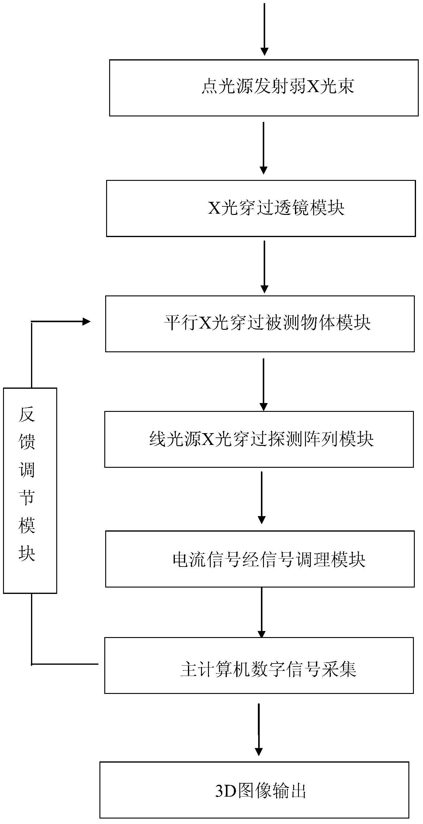
[0039] A weak X-ray 3D imaging method of the present invention, the current signal generated after passing through the detector array module is an extremely weak current analog signal, the signal passes through the signal conditioning module, and the current signal is converted into a voltage signal by the signal conditioning circuit, an...


PUM


Abstract

The invention discloses a weak X-ray 3D (three-dimensional) imaging method. The used device is mainly composed of a weak X-ray radiation source, a lens module, a detected object module, a detection array module, a signal conditioning module, a host computer and a feedback adjusting module. The method comprises the following steps: step one, firstly emitting a beam from the weak X-ray radiation source; step two, enabling the X-ray beam emitted from the step one to pass through the lens module to convert into a parallel beam; step three, converting the parallel beam into the line source X-ray after passing through the detected object module; step four, converting the line source X-ray into a current signal after passing through the detection array module; step five, converting the current signal into a digital signal through the signal conditioning module; step six, acquiring the digital signal by the host computer; step seven, performing the feedback adjusting on the detected object module by the host computer; and step eight, outputting a 3D image through the host computer. The normal point X-ray source is converted into the line X-ray source through the method disclosed by the invention so that the detected image signal is a linear signal, the operation is convenient and the efficiency is high.

Description

technical field [0001] The invention belongs to the field of detection and imaging, and relates to an imaging method for biological tissues such as microorganisms by using a weak X light source below 100KeV. Background technique [0002] Industrial CT technology is the abbreviation of industrial computerized tomography technology. It can clearly, accurately and intuitively display the internal structure of the detected object in the form of two-dimensional tomographic images or three-dimensional images without damage to the detected object. Composition, material and defect status are the most widely used non-destructive testing techniques at present. Compared with other non-destructive testing methods, industrial CT has high measurement accuracy and good imaging quality, and is widely used in the industrial field of product internal defect analysis. However, if the light source uses weak X-rays to detect and collect workpieces, since the energy of the weak X-rays is small, ...

Claims


Application Information

Patent Timeline
Patent Type & Authority Applications(China)
IPC IPC(8): G01N23/04
Inventor 焦志伟刘迎林张有忱丁玉梅杨卫民
Owner BEIJING UNIV OF CHEM TECH
Why Eureka
Try Eureka