Electric transmission line carbon fiber composite core manufacturing method

A technology for power transmission lines and manufacturing methods, applied in the direction of cable/conductor manufacturing, circuits, electrical components, etc., to achieve the effects of weight reduction, high conductivity, and reasonable equipment configuration

Inactive Publication Date: 2013-11-27
SUZHOU SUYUE NEW MATERIAL
View PDF5 Cites 23 Cited by
  • Summary
  • Abstract
  • Description
  • Claims
  • Application Information

AI Technical Summary

Problems solved by technology

[0003] The purpose of the present invention is to provide a carbon fiber composite core manufacturing method for power transmission line cables in view of the urgent need for carbon fiber composite cores in power transmission lines

Method used


Image

  • Electric transmission line carbon fiber composite core manufacturing method
  • Electric transmission line carbon fiber composite core manufacturing method

Examples


Embodiment 1

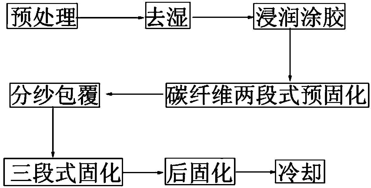
[0031] A method for manufacturing a carbon fiber composite core for a power transmission line, comprising the steps of:

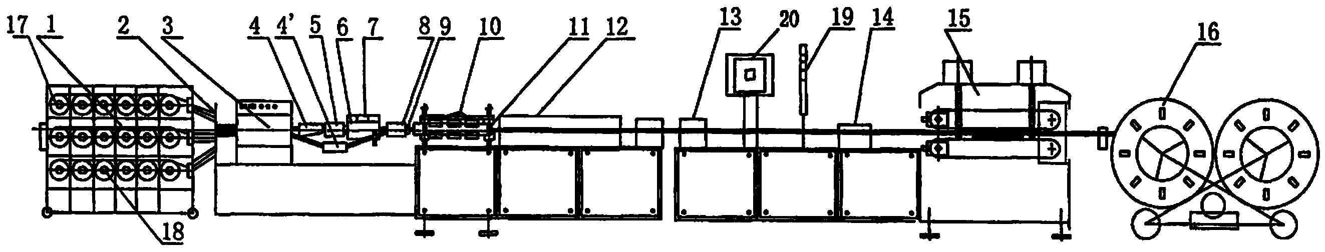
[0032] Step 1: Provide a carbon fiber composite core manufacturing equipment for power transmission lines, the equipment includes: creel, yarn collector, dehumidifier, carbon fiber impregnator, high-strength glass fiber impregnator, front mold yarn guide, front mold , front mold heater, front mold yarn splitter, rear mold yarn guide, heater, rear mold, post curing heater, air cooling device;

[0033] Step 2: Pretreatment: adjust the tension and straightness of carbon fiber and high-strength glass fiber or basalt fiber, so that the tension of carbon fiber and high-strength glass fiber or basalt fiber is consistent and meets the process requirements, with good straightness;

[0034] Step 3: Dehumidification: pull out carbon fiber and high-strength glass fiber or basalt fiber from the creel at a constant speed, let it pass through the yarn collector and enter ...

Embodiment 2

[0042] In this embodiment, except for the following process conditions, other process steps are the same as in Example 1.

[0043] In step 3, the fiber moisture content is not more than 3%;

[0044] In step 4, the moving speed of the immersion coating is controlled at 400mm / min;

[0045] In step 5, the heating temperature of one section close to the front mold yarn guide is 35°C, the heating temperature of the other section is 70°C, and the distance between the two heating sections is kept at 20cm;

[0046] In step 7, the heating temperature distribution of the three heating zones is 95°C, 165°C and 155°C, and the intervals between the three heating zones are 20cm;

[0047] In step 8, the post-curing temperature is 180° C., and the post-curing time is 3 minutes.

Embodiment 3

[0049] In this embodiment, except for the following process conditions, other process steps are the same as in Example 1.

[0050] In step 3, the fiber moisture content is not more than 3%;

[0051] In step 4, the moving speed of the immersion coating is controlled at 600mm / min;

[0052] In step 5, the heating temperature of the section close to the front mold yarn guide is 45°C, the heating temperature of the other section is 90°C, and the distance between the two heating sections is kept 40cm;

[0053] In step 7, the heating temperature distribution of the three heating zones is 110°C, 175°C and 170°C, and the intervals between the three heating zones are 40cm;

[0054] In step 8, the post-curing temperature is 200° C., and the post-curing time is 8 minutes.


PUM

PropertyMeasurementUnit
tensile strengthaaaaaaaaaa
shear strengthaaaaaaaaaa
diameteraaaaaaaaaa

Abstract

An electric transmission line carbon fiber composite core manufacturing method mainly includes the following steps of conducting preprocessing, dehumidification and glue infiltration, pre-hardening carbon fibers in a two-section heating mode, enabling high-strength glass fibers or basalt fibers to cover a pre-hardened carbon fiber core according to certain rules, hardening the carbon fiber core covered by the high-strength glass fibers or the basalt fibers in a three-section mode, and conducting post curing and cooling, wherein consumed epoxy resin is high-temperature-resistant special type pultrusion epoxy resin which is prepared by adding modified anhydride compounds in the glue infiltration process. The electric transmission line carbon fiber composite core manufacturing method has the advantages that the carbon fibers are preformed in a pultrusion mode to be in a semi-hardened state after being infiltrated, heating temperature sections are controlled so that the carbon fiber core with excellent performance can be obtained, particularly, heating and hardening are conducted in the three-section mode in the final covering and forming process, therefore, the rigidity of final products is ensured, the smoothness of production and production efficiency are improved, and the carbon fiber composite core produced through combination can completely meet the requirements of electric power transmission.

Description

technical field [0001] The invention relates to a manufacturing method of a core wire bearing the weight of a cable between two iron towers in a power transmission line, in particular to a manufacturing method of a composite material core wire, in particular to a manufacturing process of a carbon fiber composite core of a power transmission line. Background technique [0002] Since 1800, there have been few major innovations in the wires used for overhead power transmission. Among them, steel-cored aluminum wires have been used the most, as the steel strands that bear the weight of overhead power transmission cables. Magnetic loss and thermal effects cause line loss in the output line. In addition, the tensile strength of the steel strand is not high enough to bear the weight of ice and snow, and it is easy to cause the tower to collapse in bad weather. For this reason, according to the characteristics of composite materials, some people proposed to use carbon fiber composit...

Claims


Application Information

Patent Timeline
Patent Type & Authority Applications(China)
IPC IPC(8): H01B13/00
Inventor 陆鸽俞小东
Owner SUZHOU SUYUE NEW MATERIAL
Why Eureka
Try Eureka