Grid-control cold cathode X-ray tube

An X-ray tube and cold cathode technology, which is applied in the field of X-ray tubes, can solve the problems of complex ray tube assembly process, many electrons intercepted by the grid, and difficulty in realizing a small focus, and achieves low cost, small focus, and prevention of inter-electrode strikes. fire effect

Inactive Publication Date: 2013-11-27
南京康众光电科技有限公司
View PDF11 Cites 7 Cited by
  • Summary
  • Abstract
  • Description
  • Claims
  • Application Information

AI Technical Summary

Problems solved by technology

Through patent retrieval, there are currently 8 patents for X-ray tubes using cold cathodes as electron sources in China: 1. Patent 03127012.3, "A New Type of Field Emission Medical Miniature X-ray Tube". The X-ray tube involved in this patent has no Electron beam converging function makes it difficult to realize small focus; 2. Patents CN201378580Y, CN201378579Y, CN101521135B, CN101494149A and CN101101848B, "Grid-controlled carbon nano cathode field emission X-ray tube, the ray tube assembly process involved in this patent is complicated and the cost is high; 3 , patent CN101494150A, the ray tube designed by this patent, the grid type is a planar grid, the field emission material used in this structure is zinc oxide, and the emission performance is poor; 4, the patent CN1553473A, the anode voltage of this patent is too low, and the ray penetration is poor
[0005] Judging from the existing technology, the current gate-controllable X-ray tubes have certain limitations, mainly in the following aspects: (1) Complex assembly process; (2) No electron beam convergence; (3) Grid control intercepted electrons etc.

Method used


Image

  • Grid-control cold cathode X-ray tube
  • Grid-control cold cathode X-ray tube

Examples


Embodiment Construction

[0031] specific implementation plan

[0032] The present invention will be further described below in conjunction with the accompanying drawings.

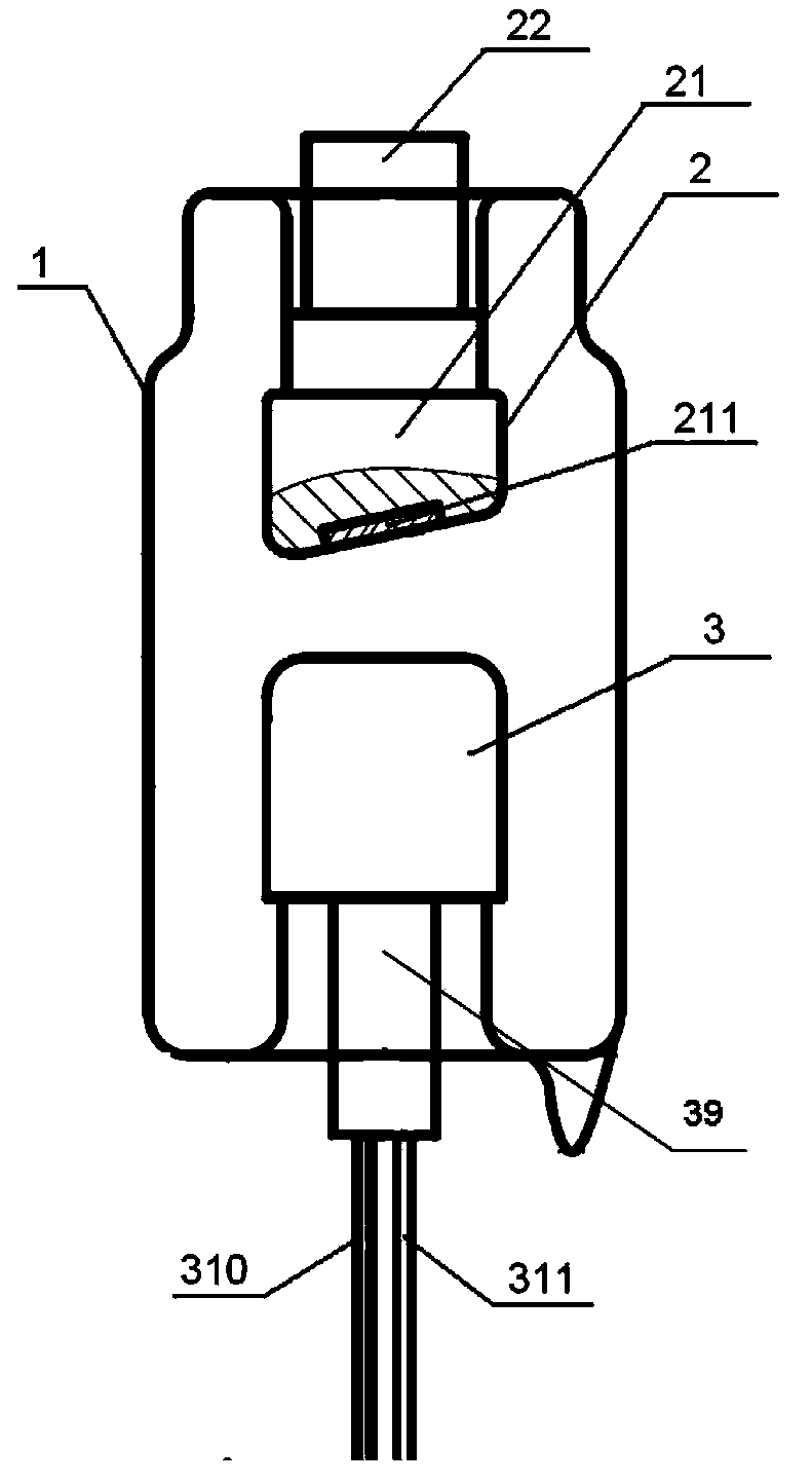
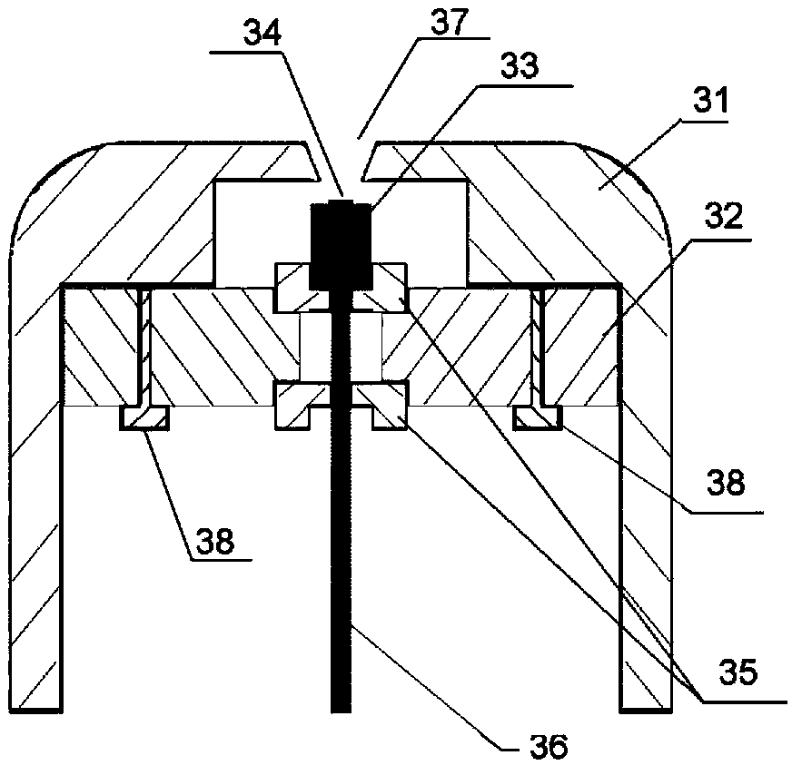
[0033] The gate-controllable cold-cathode X-ray tube of the present invention utilizes the excellent electron emission performance of the cold cathode, and packages it in a vacuum container as a part of the cathode assembly. The high electric field formed by the gate voltage on the surface of the cold cathode field emitter excites the electron beam from the inside of the emitter. A voltage of 0-3000V is applied between the grid substrate and the emitter electrode to excite electrons from the cold cathode emitter.

[0034] In the grid-controllable cold cathode X-ray tube, the high voltage is introduced through the anode connection column, the cathode cover can be used as a grid control electrode, and is connected to a grid lead-out electrode, the cathode base is connected to the cathode connection rod, and connected to the cathode ...


PUM


Abstract

The invention relates to a grid-control cold cathode X-ray tube which comprises a vacuum cavity, an anode assembly, a grid-control electrode and a cathode assembly. The anode assembly comprises an anode target, an anode metal hood and an anode connection pillar. The anode target, the anode metal hood and the cathode assembly are packaged in the vacuum cavity. The anode target is embedded in the anode metal hood and used for producing X rays. The normal line of a plane of the anode target is connected with an anode and a cathode to form an inclination angle which is (12+ / -1) degrees. The cathode assembly comprises a cathode substrate and a cathode material which is arranged on the cathode substrate. The cathode hood serving as the grid-control electrode covers a cathode installation part which comprises a cathode lead and a grid lead. The cathode hood is made of metal. A hole is formed in the cathode hood and located in the connection line of the cathode substrate and the anode target. High voltage is led in through the anode connection pillar. The cathode hood serving as the grid-control electrode is connected with the grid lead. The cathode substrate is connected with the cathode lead. Voltage is exerted between two electrodes led out from the grid lead and the cathode lead.

Description

technical field [0001] The invention relates to an X-ray tube, in particular to a gate-controlled cold-cathode X-ray tube and its assembly method. technical background [0002] An X-ray tube is a device that allows the controlled emission of X-rays. They are used in various systems, for example, X-ray imaging technology in medical, industrial and security fields, spectral analysis (X-ray fluorescence spectroscopy, X-ray photoelectron spectroscopy), X-ray diffraction analysis, etc. The principle of generating X-rays in a ray tube is to use high-energy electrons (tens of thousands of electron volts) to bombard a metal target. The interaction between these electrons and the target is multiplied until X-rays are emitted. The X-ray intensity is directly proportional to the electron flow on the target material. The penetration of X-rays is directly proportional to the applied voltage on the target material. The emission area of ​​X-rays is determined by the range of electron b...

Claims


Application Information

Patent Timeline
IPC IPC(8): H01J35/04H01J35/06H01J35/08H01J35/14
Inventor 张研刘春毅屈科
Owner 南京康众光电科技有限公司
Why Eureka
Try Eureka