Oil field fuel coal steam-injection boiler

A steam injection boiler and coal-fired technology, which is applied to steam boilers, steam generation, mining fluids, etc., can solve the problems of high cost and poor economy, and achieve the effects of reducing mining costs, reducing steam humidity, and improving thermal efficiency

Active Publication Date: 2013-12-04
BC P INC CHINA NAT PETROLEUM CORP +1
View PDF5 Cites 2 Cited by
  • Summary
  • Abstract
  • Description
  • Claims
  • Application Information

AI Technical Summary

Problems solved by technology

[0003] In order to solve the problems of high cost and poor economy of existing fuel oil and gas-fired steam injection boilers, the present invention provides a coal-fired steam injection boiler for oil fields

Method used


Image

  • Oil field fuel coal steam-injection boiler
  • Oil field fuel coal steam-injection boiler
  • Oil field fuel coal steam-injection boiler

Examples


Embodiment 1

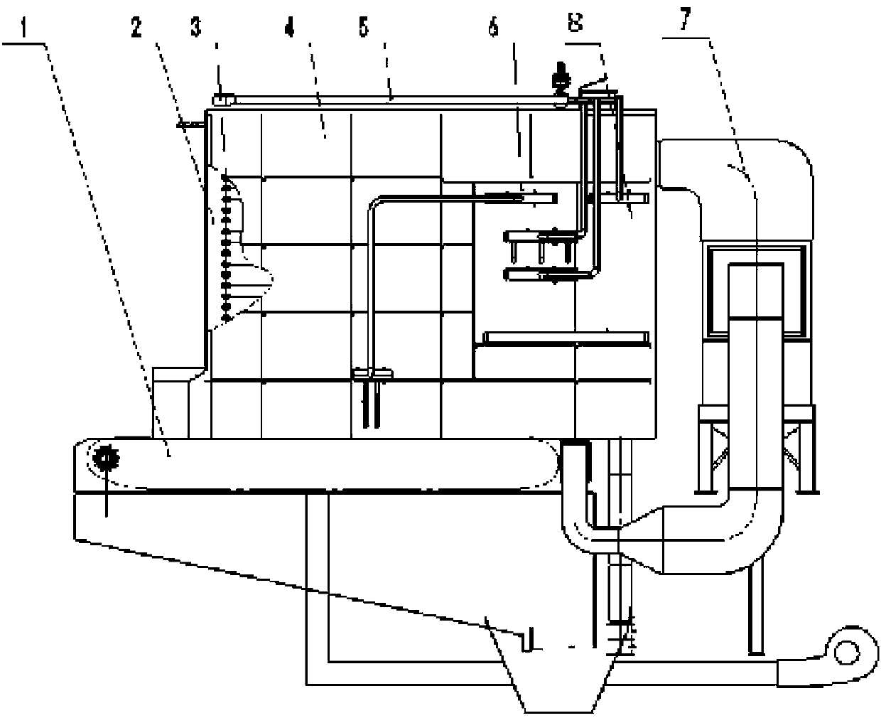
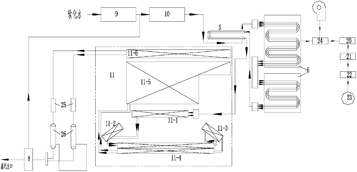
[0024] Embodiment 1: The water treated by the water treatment tank 9 does not contain Ca and Mg ions (that is, contains Na, K, Cl and other ions). The inlet end of the plunger pump 10 is connected to a water treatment tank 9, and the water treated by the water treatment tank 9 is boosted by the plunger pump 10 and injected into the outer pipe of the water heat exchanger 5, and the water in the outer pipe of the water heat exchanger 5 flows through the convection section 6. The water heated by the convection section 6 enters the inner tube of the water heat exchanger 5, and the water in the inner tube of the water heat exchanger 5 can heat the water in the outer tube at the same time, and the water in the inner tube enters the furnace body 11 after heat exchange, followed by After the middle arch pipe 11-1 and the front arch pipe 11-2 enter the anti-scorch pipe 11-4, the water flowing out from the anti-scorch pipe 11-4 flows back to the anti-scorch pipe 11-4 after passing throug...

Embodiment 2

[0027]Embodiment two: the water treated by the water treatment tank 9 does not contain Ca, Mg, Na, K, Cl plasma, and the water is injected into the outer pipe of the water heat exchanger 5 after the plunger pump 10 boosts the pressure, and the water heat exchanger 5 The water in the outer pipe flows through the convection section 6, and the water heated by the convection section 6 enters the inner pipe of the water heat exchanger 5, and the water in the inner pipe of the water heat exchanger 5 enters the furnace body 11 after exchanging heat with the water of the outer pipe, and is heated by the furnace. The water flowing out of the body 11 directly enters the superheater 8 to form steam to be discharged, and the separated water is injected back into the plunger pump 10 . Since the water in the whole process does not contain Na, K, Cl plasma, the high-efficiency steam-water separator 26 is omitted in this process, and the water flowing out from the furnace body 11 can directly ...


PUM


Abstract

Provided is an oil field fuel coal steam-injection boiler. The problem that an existing fuel oil and fuel gas steam-injection boiler is high in cost and bad in economy is mainly solved. The oil field fuel coal steam-injection boiler is characterized in that an inlet end of a plunger pump (10) is connected with a water processing tank (9), water processed by the water processing tank (9) is subjected to pressure rising thought the plunger pump (10) and then is injected to an outer pipe of a water heat exchanger (5), water of the outer pipe of the water heat exchanger (5) flows through a convection section (6), is heated by the convection section (6) and then enters an inner pipe of the water heat exchanger (5), then the water enters a boiler body (11), water which flows out of the boiler body (11) enters a high-efficiency steam-water separator (26), separated steam enters a superheater (8), generated steam is exhausted, and water separated by the high-efficiency steam-water separator (26) is injected back to the plunger pump (10). The oil field fuel coal steam-injection boiler can provide superheated steam with low moisture and high temperature, so that requirements for thickened oil extraction are better met, heat efficiency is high, operation is easy, operation is stable, and fault rate is low.

Description

technical field [0001] The invention relates to a steam-injection boiler used for thermal recovery of underground heavy oil and super-heavy oil during crude oil exploitation, in particular to a coal-fired steam-injection boiler in an oil field. Background technique [0002] As oil resources gradually enter the fields of human life and social interaction, global oil consumption is increasing rapidly, thin oil resources are decreasing day by day, and oil prices are rising. People are turning their attention to the development of abundant heavy oil resources. Thermal recovery steam injection boiler, as the key core equipment of heavy oil recovery technology, is widely used in major oil fields at home and abroad. At present, the oilfield steam injection boilers operating in various oil regions mainly use crude oil and natural gas as fuel to generate steam that meets the requirements of the extraction process to realize the development and utilization of heavy oil resources. An...

Claims


Application Information

Patent Timeline
Patent Type & Authority Applications(China)
IPC IPC(8): F22B31/08F22B37/34E21B43/24
Inventor 周英吴永宁朱进礼邓晓友赵晶晶穆名陈季赵艳春任为侯君杨帆李慧王列裴明东宋云鹏霍恩达李龙李轩宇国聪齐武
Owner BC P INC CHINA NAT PETROLEUM CORP
Why Eureka
Try Eureka