
Reflection type beam splitting raster and interference photolithographic system

A spectroscopic grating and reflective technology, applied in the field of lithography, can solve the problems of manufacturing difficulty and cost increase, poor graphic quality, limited lithographic format, etc., and achieve the effect of pixelation control, graphic quality improvement, and simple and reliable structure

Inactive Publication Date: 2013-12-04
SUZHOU UNIV
View PDF4 Cites 6 Cited by
  • Summary
  • Abstract
  • Description
  • Claims
  • Application Information

AI Technical Summary

Problems solved by technology

Generally suitable for optical laboratories, not for optical processing equipment
Second, the lithography format is limited
If the aperture of the beam expander is to be increased, the manufacturing difficulty and cost will increase significantly
Third, the pattern quality of the edge of the photolithographic area is poor
[0018] First: ±1 order diffraction efficiency needs to be improved
Second: Sufficient suppression of useless diffraction orders (orders 0 and above 2) cannot be achieved
Its exposure area is not easy to achieve precise splicing exposure, which limits the solution's application in large-format lithography

Method used

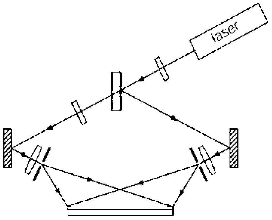
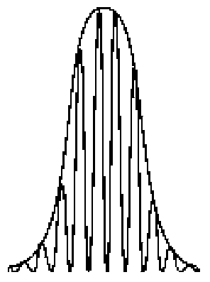
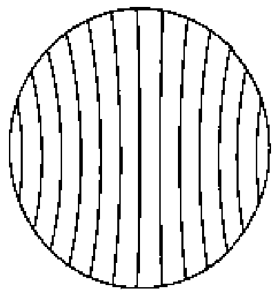

Image

  • Reflection type beam splitting raster and interference photolithographic system
  • Reflection type beam splitting raster and interference photolithographic system
  • Reflection type beam splitting raster and interference photolithographic system

Examples


Embodiment Construction

[0053] As mentioned in the background technology, in the existing interference lithography process, when a diffraction grating is used as a spectroscopic device, due to the defects of low diffraction efficiency of the diffraction grating and insufficient suppression of useless diffraction orders, the interference image during exposure has irregular fringes. Issues with sharpness and edge distortion.

[0054] Therefore the object of the present invention is to propose a kind of reflective spectroscopic grating applied in the interference lithography process and the interference lithography technology using the spectroscopic grating, the reflective spectroscopic grating can improve the ±1st order diffraction efficiency of the diffraction grating, Suppressing the diffracted light energy of other orders, especially the efficiency of 0-order light and ±2-order light, makes the ±1-order diffraction efficiency of the grating reach more than 92%, which is obviously better than the diff...


PUM


Abstract

The invention discloses a reflection type beam splitting raster and an interference photolithographic system. The reflection type beam splitting raster comprises a raster groove-shaped area located on a reflection face and a light blocking area located on the periphery of the raster groove-shaped area. The raster groove-shaped area comprises raster structures which are distributed periodically. Each raster structure comprises a groove-shaped reflection face and a non-reflection face. An inclined angle is formed between the groove-shaped reflection face and a raster base face. The reflection type beam splitting raster can realize largest modulation on +-1-level light, and enables reflected beam splitting light to have a highest energy utilization rate. An interference pattern obtained through the reflection type beam splitting raster has good boundary quality, is capable of finishing precise spliced patterns, and enables the large-width interference photolithographic technology to be improved remarkably.

Description

technical field [0001] The invention relates to the technical field of photolithography, in particular to a spectroscopic grating used in the interference photolithography technology and an interference photolithography system formed by using the spectroscopic grating. Background technique [0002] Interference lithography is an important branch of lithography, which has received extensive attention in recent years. The main advantage of interference lithography is the high pattern resolution that can be achieved. When the wavelength λ and numerical aperture NA of the optical system are fixed, the minimum linewidth that the interference optical system can obtain is λ / (4NA), which is 1 / 2 of the ordinary projection imaging optical system. In addition, the optical path of interference lithography is simple, and the pattern produced has accurate cycle and good uniformity. [0003] There are two typical optical path schemes in interference lithography. Optical path scheme one ...

Claims


Application Information

Patent Timeline
IPC IPC(8): G02B5/18G03F7/20
CPCG02B5/1861G03F7/70408
Inventor 胡进浦东林陈林森
Owner SUZHOU UNIV
Learn More