Variable inertia flywheel structure

A technology of variable inertia and flywheel, which is applied in the field of variable inertia flywheel structure, can solve problems such as jitter, slow switching of high-speed speed, poor acceleration performance, etc., to improve smoothness and uniformity of operation, reduce flywheel moment of inertia, and fast speed switching Effect

Active Publication Date: 2013-12-11
ZHEJIANG GEELY AUTOMOBILE RES INST CO LTD +1
View PDF5 Cites 15 Cited by
  • Summary
  • Abstract
  • Description
  • Claims
  • Application Information

AI Technical Summary

Problems solved by technology

[0003] When the flywheel inertia is large, the high-speed speed switching is slow, the acceleration performance is poor, and the fuel consumption is high; when the flywheel inertia is small, the engine is low-speed or idling is not stable, causing problems such as jitter
In the prior art, the flywheel inertia is a fixed value and cannot be changed, and the flywheel cannot meet the above requirements at the same time

Method used


Image

  • Variable inertia flywheel structure
  • Variable inertia flywheel structure
  • Variable inertia flywheel structure

Examples


Embodiment Construction

[0021] An embodiment of the present invention provides a variable inertia flywheel structure.

[0022] In order to make the object, technical solution and advantages of the present invention clearer, the implementation manner of the present invention will be further described in detail below in conjunction with the accompanying drawings.

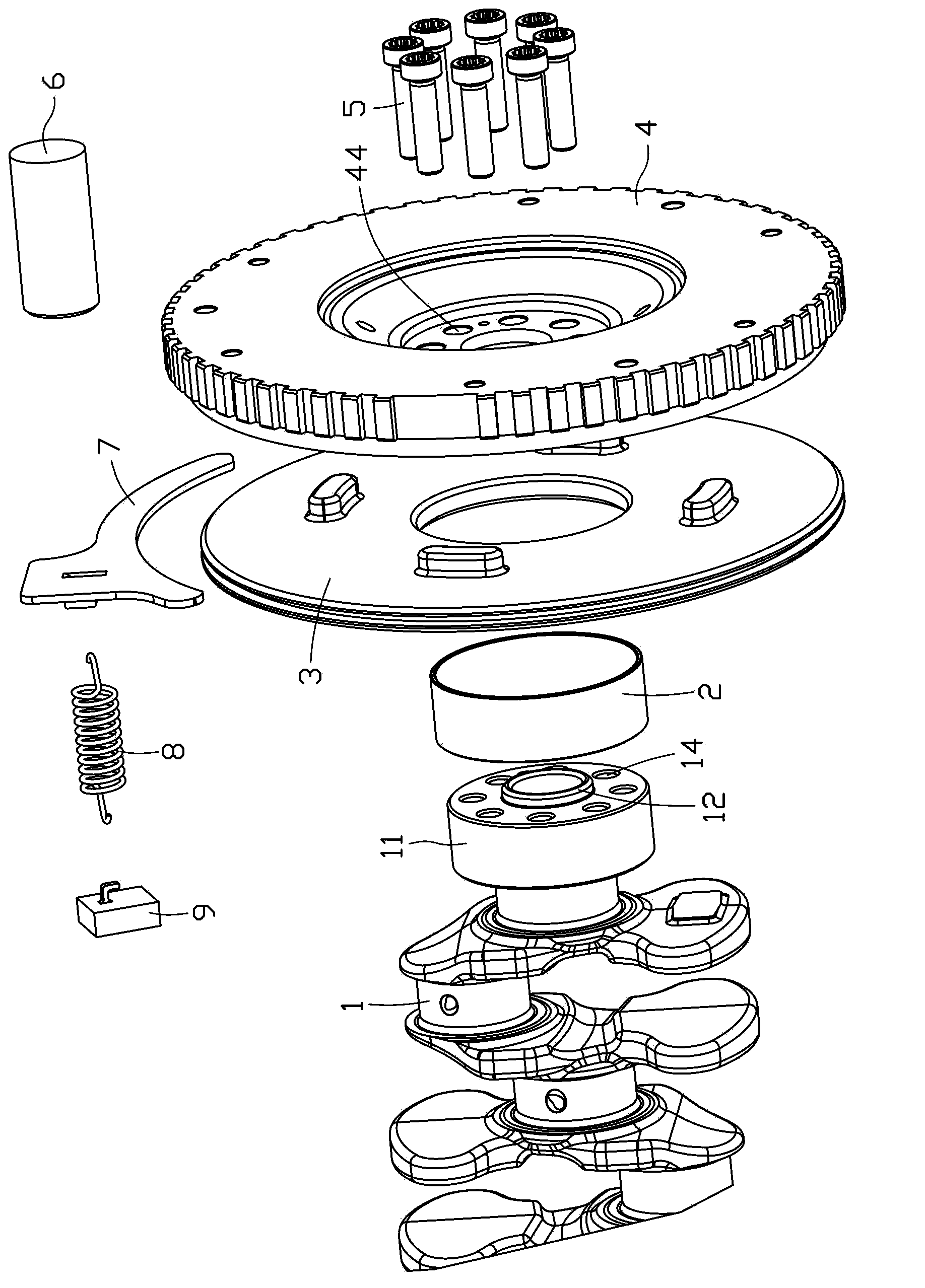
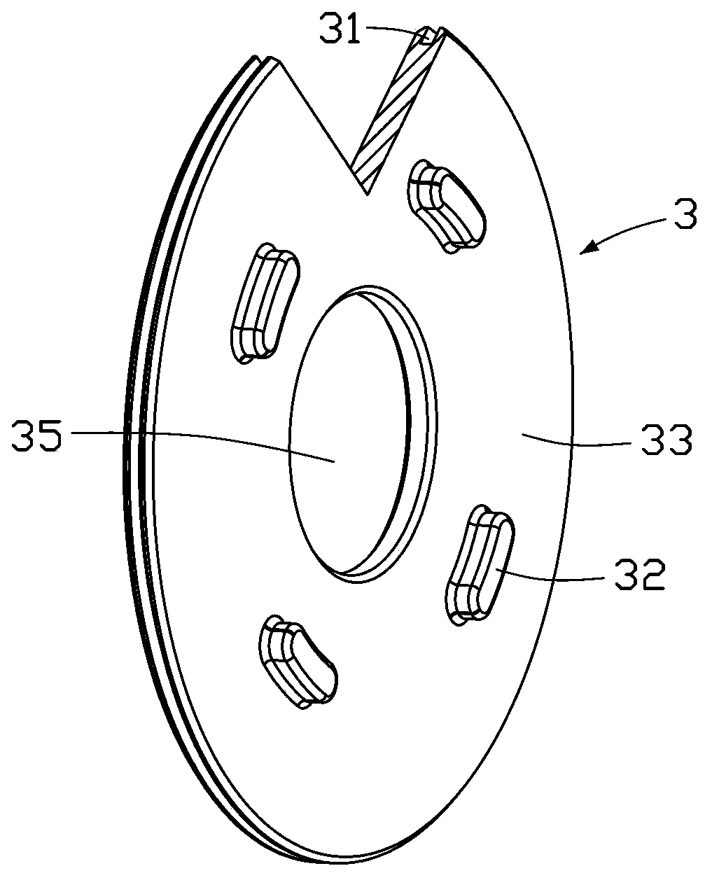
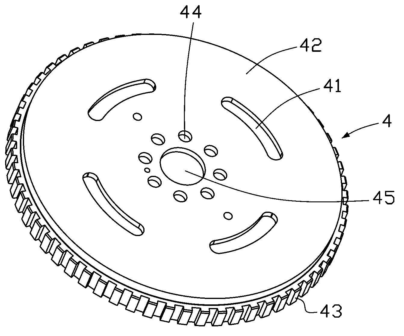
[0023] Please refer to Figure 1 to Figure 4 , is a structural schematic diagram of the variable inertia flywheel structure provided by the embodiment of the present invention. The variable inertia flywheel structure includes a crankshaft 1, a bush 2, a first flywheel 4, a second flywheel 3, bolts 5, a solenoid valve 6, and a shift fork 7 , return spring 8, positioning block 9.

[0024] The front end of the crankshaft 1 includes a flange 11 and a positioning lip 12, wherein the positioning lip 12 protrudes from the front end face of the flange 11, and the outer circle of the positioning lip 12 matches the inner hole 45 of the first flywheel...


PUM


Abstract

The embodiment of the invention discloses a variable inertia flywheel structure, which comprises a first flywheel and a second flywheel, wherein the first flywheel is used for being fixedly connected with a crankshaft, and the first flywheel comprises a first flywheel disk; the second flywheel comprises a second flywheel disk, and a pawl slot is arranged on a disc surface of one of the first flywheel disk and the second flywheel disk; and a pawl is convexly arranged on a disc surface of the other one of the first flywheel disk and the second flywheel disk, and the pawl is correspondingly matched with the pawl slot. When the large inertia of the flywheel is needed, the pawl extends into the pawl slot, and the first flywheel drives the second flywheel to rotate together; when the small inertia of the flywheel is needed, the pawl is separated from the pawl slot, and the first flywheel rotates and the second flywheel does not rotate with the first flywheel. According to the variable inertia flywheel structure, when an engine runs at low speed, the inertia of the flywheel increases so as to improve the smoothness of operation; and when the engine runs at high speed, the moment of inertia of the flywheel is reduced, and the fuel consumption is saved.

Description

technical field [0001] The invention relates to parts of automobiles, in particular to a variable inertia flywheel structure. Background technique [0002] The flywheel is the energy storage device of the engine, and the greater the inertia of the flywheel, the greater the stored energy. When the engine speed is low, the flywheel releases the stored energy to improve the running smoothness and uniformity of the engine, which is particularly obvious; Well, it's an ambivalent relationship. [0003] When the flywheel inertia is large, the high-speed speed switching is slow, the acceleration performance is poor, and the fuel consumption is high; when the flywheel inertia is small, the engine is not stable at low speed or idle speed, causing problems such as vibration. In the prior art, the inertia of the flywheel is fixed and not variable, and the flywheel cannot meet the above requirements at the same time. Contents of the invention [0004] The embodiment of the present i...

Claims


Application Information

Patent Timeline
Patent Type & Authority Applications(China)
IPC IPC(8): F16F15/31
Inventor 王浩由毅沈源袁爽冯擎峰
Owner ZHEJIANG GEELY AUTOMOBILE RES INST CO LTD
Why Eureka
Try Eureka