Optical fiber measurement method and device of blade tip clearance

A technology of optical fiber measurement and blade tip clearance, applied in the direction of measuring devices, optical devices, instruments, etc., can solve the problems of poor measurement accuracy, large measurement errors, interference of blade tip radiation spectrum, etc., and achieve the effect of high sensitivity

Active Publication Date: 2013-12-11
INST OF ENGINEERING THERMOPHYSICS - CHINESE ACAD OF SCI
View PDF9 Cites 30 Cited by
  • Summary
  • Abstract
  • Description
  • Claims
  • Application Information

AI Technical Summary

Problems solved by technology

As for the optical fiber displacement measurement technology, the earliest method is to use one optical fiber to emit the measuring laser and one optical fiber to receive the reflected light signal. This measurement method is easily affected by the fluctuation of the emitting light source, the loss of the optical fiber and the reflectivity of the measured surface, so the measurement accuracy is poor.
In order to solve the above problems, the reflection compensation optical fiber displacement testing technology was developed later. One signal fiber and one reference fiber are

Method used


Image

  • Optical fiber measurement method and device of blade tip clearance
  • Optical fiber measurement method and device of blade tip clearance
  • Optical fiber measurement method and device of blade tip clearance

Examples


Embodiment Construction

[0042] The invention can measure the tip clearance of the high-speed rotating blade at high temperature, has the function of compensating the small inclination angle of the measured surface, and provides detailed and reliable data for the active control of the tip clearance of the ground gas turbine or aeroengine.

[0043] The technical solution of the present invention will be described in detail below in conjunction with the embodiments and the accompanying drawings.

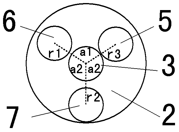
[0044] Please combine Figure 1-Figure 3 .

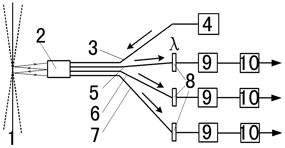
[0045] figure 1 It is the principle diagram of the multi-point positioning reflection compensation type optical fiber ranging of the present invention (this embodiment takes three as examples), the self-temperature-controlling laser 4 emits a laser with a certain working wavelength in the working band between 300-450nm, and the coupling Enter the transmitting optical fiber 3, transmit to the measured surface 1 through the optical fiber probe 2, return to the optic...


PUM


Abstract

Provided is an optical fiber measurement method and device of blade tip clearance. A multipoint orientation reflecting compensation type optical fiber is adopted to carry out distance measurement; laser emitted by a laser device in a working wavelength range is transmitted to the surface of an object to be measured through a fiber probe, is reflected back to the fiber probe after being reflected through the surface of the object to be measured, and then enters multiple channels of receiving optical fibers respectively; filtering is carried out on laser entering the receiving optical fibers through optical filters, energy of laser entering the multiple channels of receiving optical fibers in the working wavelength range after the laser is reflected by the surface of the object to be measured is obtained respectively, the energy of the laser is converted into weak current signals through photoelectric detection, the weak current signals are amplified into current or voltage signals for being collected through a signal amplification filtering circuit, comparison processing is carried out by collecting the multiplexed output current signals or voltage signals, and the distance between the optical fiber probe and the object to be measured is obtained. The invention further discloses a measurement device for achieving the method.

Description

technical field [0001] The invention relates to a method for measuring blade tip clearance optical fiber. [0002] The invention also relates to a measuring device for carrying out the method described above. Background technique [0003] Turbine moving blade tip clearance is an important parameter that affects the performance of ground gas turbines or aero-engines. If the clearance is too large, the gas leakage flow will increase, resulting in a decrease in the efficiency of the gas turbine or aero-engine and an increase in fuel consumption; a decrease in the clearance will easily lead to contact between the blade and the casing. , causing blade wear or even damage. Because the influencing factors of the blade tip clearance are quite complex, it is difficult to determine by calculation and analysis alone, so the clearance must be measured in the test to provide reliable data for the control of the blade tip clearance. Real-time monitoring of gaps, diagnosis and early warn...

Claims


Application Information

Patent Timeline
IPC IPC(8): G01B11/14
Inventor 李勋锋淮秀兰成克用周小明蔡军
Owner INST OF ENGINEERING THERMOPHYSICS - CHINESE ACAD OF SCI
Why Eureka
Try Eureka