
Fiber optic sensor realizes precise measurement of metal stress and strain

A fiber optic sensor and metal stress technology, applied in measuring devices, instruments, optical devices, etc., can solve the problems that affect the accuracy of strain measurement and long-term stability, the temperature effect is difficult to eliminate accurately, and the shear resistance is very poor, etc., to achieve long-term Improved accuracy and environmental adaptability, good strain measurement unidirectionality, and improved long-term stability

Active Publication Date: 2016-12-07
SHANGHAI BAIANTEK SENSING TECH CO LTD
View PDF6 Cites 0 Cited by
  • Summary
  • Abstract
  • Description
  • Claims
  • Application Information

AI Technical Summary

Problems solved by technology

Among them, the precise measurement of stress and strain of metal structures is one of the most important applications of optical fiber sensing technology, such as steel structure safety monitoring and early warning, metal material mechanical performance testing, vehicle and aircraft aerodynamic characteristics prediction, load weighing, etc. However, because the optical fiber is very thin (usually no more than 1mm in diameter), its main component is SiO2, so it is particularly fragile, especially its shear resistance is very poor, and it cannot meet the extensive construction requirements of engineering structures and the field when it is directly used in actual engineering. Long-term durability requirements in harsh environments. Therefore, it is necessary to design a reasonable packaging structure. First, the optical fiber package is fixed on an elastic substrate to form a strain sensor, which can detect and calibrate its temperature characteristics and strain measurement performance one by one, and is convenient for packaging, transportation, and on-site Install and use; then install and fix the strain sensor on the appropriate part of the metal structure under test at the engineering site to realize accurate measurement of stress and strain on the monitored part of the metal structure
Therefore, there are multiple strain transfer interfaces between the optical fiber and the elastic substrate, and between the strain sensor and the metal structure to be tested, and the creep or nonlinear deformation of the transfer interface itself will greatly affect the accuracy and accuracy of strain measurement. Long-term stability, and the strain measurement output is affected by temperature, resulting in a greater change in thermal output (the thermal expansion coefficient of the metal structure and the thermal expansion coefficient of the adhesive are usually much higher than the thermal expansion coefficient of the optical fiber itself), linearity And the repeatability is worse, the temperature effect is difficult to eliminate accurately

Method used


Image

  • Fiber optic sensor realizes precise measurement of metal stress and strain
  • Fiber optic sensor realizes precise measurement of metal stress and strain
  • Fiber optic sensor realizes precise measurement of metal stress and strain

Examples


Embodiment Construction

[0038] In order to understand the technical content of the present invention more clearly, the following examples are given in detail.

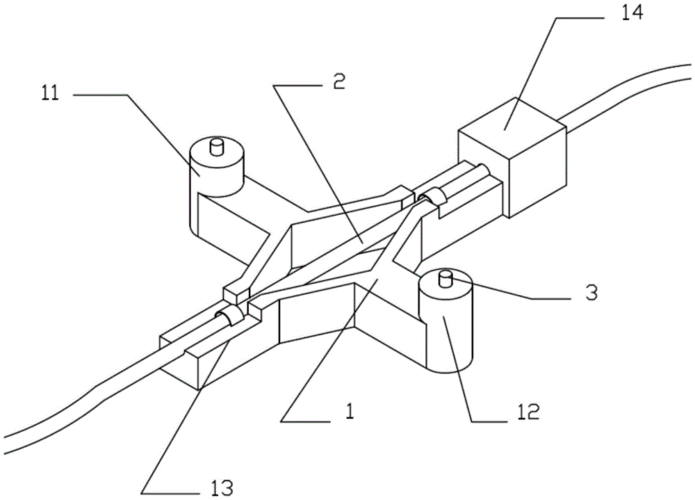
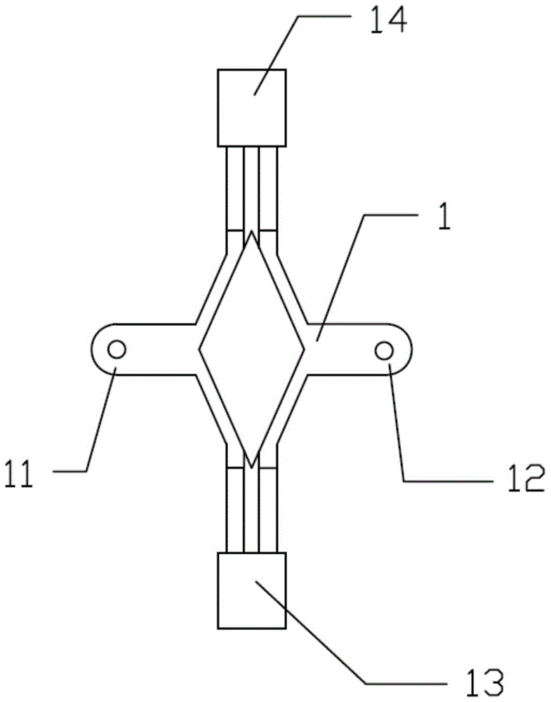
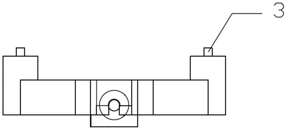
[0039] see Figure 1 to Figure 4 , the optical fiber sensor includes a strain elastic beam 1, the strain elastic beam 1 is annular, the strain elastic beam 1 has a first measurement fixed end 11 and a second measurement fixed end 12, the first measurement fixed end 11 is arranged on the strain elastic beam 1 on one side, the second measurement fixed end 12 is arranged on the other side of the strain elastic beam 1, the strain elastic beam 1 has an optical fiber fixed end, the optical fiber 2 is fixedly connected with the strain elastic beam 1 through the optical fiber fixed end, and the first measurement is fixed The line connecting the end 11 and the second measuring fixed end 12 is perpendicular to the axis of the optical fiber 2 . In order to improve the temperature compensation effect, the strain elastic beam 1 and the external metal stru...


PUM


Abstract

The invention relates to an optical fiber sensor capable of measuring stress-strain of metal accurately. The optical fiber sensor comprises a strain elastic beam provided with a first measuring fixing end and a second measuring fixing end. The connecting line of the first measuring fixing end and the second measuring fixing end is perpendicular to an axis of an optical fiber. Due to the fact that the optical fiber sensor capable of measuring the stress-strain of metal accurately adopts the structure, creep deformation caused by a traditional gluing method is changed, and long-term stability of a zero point is improved. The output of the optical fiber installed on a tested metal structural body is hardly affected by the changes of the environment temperature, and secondary compensation does not need to be carried out by utilizing an additional temperature measuring sensor. The transverse sensitivity of the optical fiber is reduced, the optical fiber is sensitive only about the stain of the strain elastic beam in the measuring direction, and the optical fiber can have good strain measurement single-direction performance. The rigidity of a strain transmission interface is guaranteed through the technology that the strain elastic beam is directly welded to the tested metal structural body, and creep deformation and non-linear deformation of the strain transmission interface are removed.

Description

technical field [0001] The invention relates to the technical field of optical fiber measuring equipment, in particular to an optical fiber sensor for realizing accurate measurement of metal stress and strain. Background technique [0002] Optical fiber sensing technology is a technology that emerged in the late 1970s. Optical fiber sensors are favored due to their superior performance, such as small size, light weight, anti-electromagnetic interference, anti-corrosion, high sensitivity, and wide measurement bandwidth. Wide, detection electronic equipment and sensors can be far apart, and can form a sensor network. The sensitivity of advanced fiber optic sensors is several orders of magnitude higher than that of traditional sensors, and can measure pressure, temperature, stress (strain), magnetic field, refractive index, deformation, microvibration, microdisplacement, sound pressure, etc. There are more than 70 kinds of physical quantities measured by technology. [0003] ...

Claims


Application Information

Patent Timeline
Patent Type & Authority Patents(China)
IPC IPC(8): G01B11/16
Inventor 钟少龙李明
Owner SHANGHAI BAIANTEK SENSING TECH CO LTD
Learn More