Compressed air energy storage system using carbon dioxide as working medium

A carbon dioxide, compressed gas technology, applied in the field of optimal utilization of energy storage technology, can solve the problems of design difficulties, complex design, difficulties, etc., to achieve the effect of optimizing power supply characteristics and improving flexibility

Active Publication Date: 2013-12-18
INST OF ENGINEERING THERMOPHYSICS - CHINESE ACAD OF SCI
View PDF11 Cites 36 Cited by
  • Summary
  • Abstract
  • Description
  • Claims
  • Application Information

AI Technical Summary

Problems solved by technology

The traditional compressed air energy storage technology uses ambient air as the working medium. When the air is compressed to a higher pressure, the design of system components such as turbomachinery and heat exchangers will be complicated and difficult, resulting in a large system scale and high cost. higher
In addition, since the air needs to be compressed to a higher pressure (not lower than 40atm) for storage, the system requires a larger volume of underground gas storage chamber or subsea chamber as a storage space to achieve constant volume storage or constant pressure storage, and once the gas is stored The

Method used


Image

  • Compressed air energy storage system using carbon dioxide as working medium
  • Compressed air energy storage system using carbon dioxide as working medium
  • Compressed air energy storage system using carbon dioxide as working medium

Examples


Embodiment Construction

[0051] In order to make the purpose, technical solution and advantages of the energy storage system clearer, the present invention will be further described in detail below with reference to the accompanying drawings and examples.

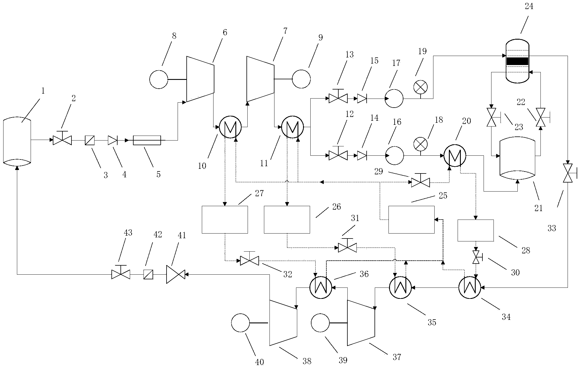
[0052] Such as figure 1As shown, the compressed gas energy storage system using carbon dioxide as the working medium of the present invention consists of an atmospheric pressure carbon dioxide storage 1, a carbon dioxide gas supply section switch valve 2, a carbon dioxide gas supply section filter 3, a carbon dioxide gas supply section check valve 4, Carbon dioxide gas supply section dryer 5, low-pressure carbon dioxide compressor 6, high-pressure carbon dioxide compressor 7, low-pressure motor 8, high-pressure motor 9, low-pressure cooler 10, high-pressure cooler 11, switch valve for liquid carbon dioxide storage section 12. Supercritical carbon dioxide storage section switch valve 13, liquid carbon dioxide storage section check valve 14, supercr...


PUM


Abstract

The invention discloses a compressed air energy storage system using carbon dioxide as a working medium. The system utilizes the supercritical characteristic of carbon dioxide and the state change characteristic of the carbon dioxide near the critical point, and the assistance by the conditions of outside environments (such as underground and seabed cavities) is not needed, so the switching of the energy storage system among constant-pressure energy storage, constant-pressure energy releasing, constant-capacity energy storage and constant-capacity energy releasing is realized, and the different types of power storage and releasing can be realized. The system utilizes the characteristic of the carbon diode which is converted from the gas state into the supercritical or liquid state, so the carbon dioxide is stored, and compared with the gas storage, the complicated degree and design difficulty of the system are effectively reduced, and the cost of the energy storage system is reduced. Meanwhile, the double-storage device method is adopted, the switching of the system between energy storage and energy releasing is flexibly completed without utilizing the assistance by the outside environments (such as underground and seabed cavities), the energy storage and energy releasing characteristics of the system are changed by controlling the carbon dioxide storage/releasing method, and the flexibility of the system is enhanced. The system can be used together with the renewable energy sources, such as solar energy and wind energy, so the generation of other pollutants is avoided, and the environment-friendly characteristic is good.

Description

technical field [0001] This system belongs to the field of optimized utilization of energy storage technology. Specifically, it is based on compressed air energy storage technology, adopts a double storage structure, and uses the state change characteristics of carbon dioxide near the critical point to achieve constant pressure or constant volume. Energy storage / energy release mode and an energy storage system that completes switching between the two. Background technique [0002] Since the Industrial Revolution, human beings have had a strong dependence on traditional energy sources such as coal and oil. However, due to the increasing carbon dioxide emissions caused by the use of traditional energy sources, the resulting greenhouse effect has seriously affected the living environment of human beings. In order to reduce the pollution of carbon dioxide to the environment, carbon dioxide capture and storage (CCS for short) technology is mostly used for the large amount of carb...

Claims


Application Information

Patent Timeline
IPC IPC(8): F01K25/04
Inventor 杨科张远李雪梅徐建中
Owner INST OF ENGINEERING THERMOPHYSICS - CHINESE ACAD OF SCI
Why Eureka
Try Eureka