
Low vacuum ejector heat pump composite waste-heat heating supply system based on huge temperature-difference heat supply network

A heating system and ejection technology, which is applied in the heating system, hot water central heating system, space heating and ventilation, etc., can solve the problem of small temperature difference between supply and return water, inflexible heating operation adjustment, and poor energy saving effect. And other issues

Inactive Publication Date: 2013-12-18
张茂勇
View PDF8 Cites 4 Cited by
  • Summary
  • Abstract
  • Description
  • Claims
  • Application Information

AI Technical Summary

Problems solved by technology

The advantages of this method are simple transformation, high efficiency of full-load operation, small investment, and good economy, but there are disadvantages such as low water supply temperature, small temperature difference between supply and return water, and inflexible adjustment of heating operation, and it is easy to damage the final stage blades. The speed is accelerated, so it is more suitable for the transformation of steam turbine units with a capacity of less than 100,000 kW, and there are few reformers for larger heating units with a capacity of 200,000 to 300,000 kW
[0004] As a type of invented heat pump, the injection heat pump is difficult to be practical in engineering due to its inherent low injection ratio and poor energy saving effect.

Method used


Image

  • Low vacuum ejector heat pump composite waste-heat heating supply system based on huge temperature-difference heat supply network

Examples


Embodiment Construction

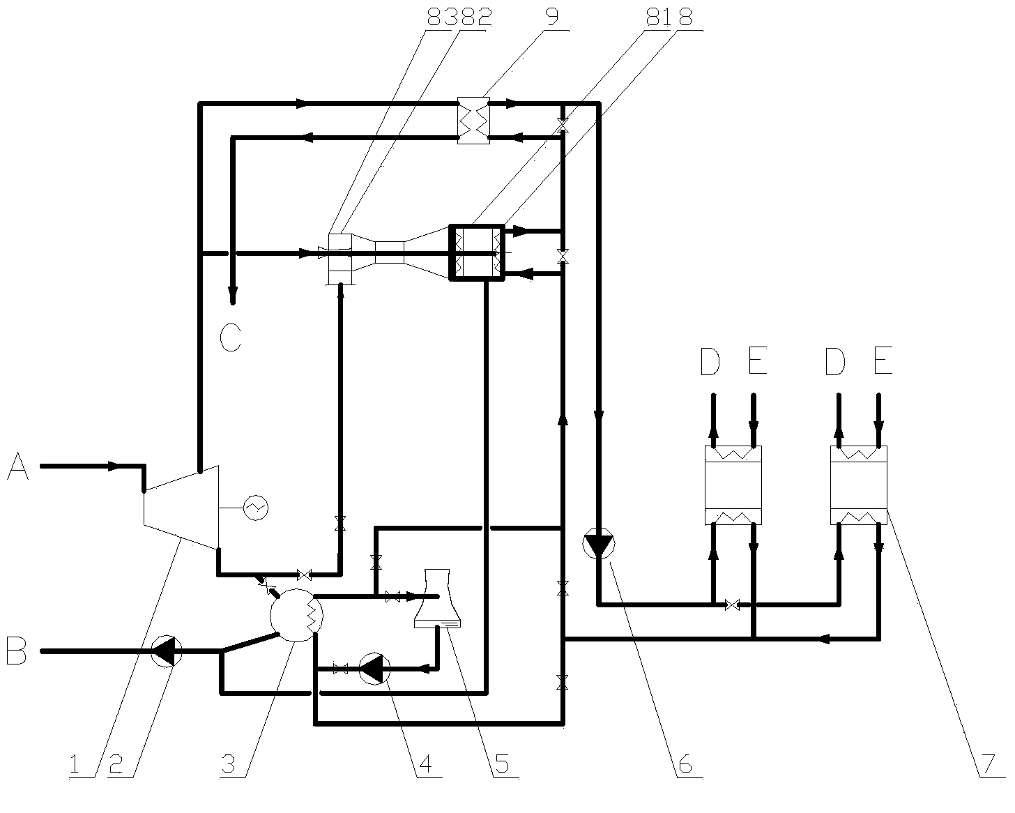
[0019] The low-vacuum injection heat pump composite waste heat heating system based on the super-large temperature difference heating network of the present invention is described in detail below with reference to the drawings and embodiments.

[0020] Concrete embodiment structure of the present invention, such as figure 1 As shown, the specific implementation and function description of this system are as follows: low-vacuum injection heat pump composite waste heat heating system based on the super-large temperature difference heating network, the system includes 8 waste heat recovery devices of the injection heat pump, as the water-based heat source of the heating network The exhaust steam direct recovery device 3, the peak regulation heater 9, the heat exchange unit with a large temperature difference in the heat network and pipeline fittings, wherein the cold side inlet of the exhaust steam direct recovery device 3 passes through the return pipe of the heat network and the...


PUM


Abstract

The invention relates to a low vacuum ejector heat pump composite waste-heat heating supply system based on a huge temperature-difference heat supply network, and belongs to the field of waste-heat recovery type combined heat and power generation based on low vacuum circulation water heating and heat exchange of an ejector heat pump. The system is characterized by comprising an ejector heat pump waste-heat recovery device, a dead-steam direct recovery device, a pitch peak heater, a heat supply network huge temperature-difference heat exchange unit and a pipe fitting, wherein the dead steam is taken as a water-based load heat source of the heat supply network; a cold-side inlet of the dead steam direct recovery device is connected with a water return pipe of the heat supply network; an outlet is connected with a heat supply network water inlet of an ejector heat pump condenser; then the dead steam is sent to the pitch peak heater to be heated to the required temperature, and then exhausted out; at last, the dead steam is sent into the dead-steam direct recovery device, and an ejection port in the ejection section of the ejector heat pump. The system can be used for a thermal power plant with higher efficiency than the conventional recovery way that waste-heat is extracted from cooling water, the utilization amount of the dead-steam waste heat can be improved by more than 1-2 times, while the investment is only a part of that of an absorption heat pump.

Description

technical field [0001] The invention belongs to the field of heat and power cogeneration based on waste heat recovery, and in particular relates to a direct waste steam recovery method and a heat supply system that combine low-vacuum waste heat recovery heat supply with thermal power plant ejection heat pump waste heat recovery heat supply. Background technique [0002] At present, the main system forms of heating in northern my country are: combined heat and power generation, regional boiler room and decentralized heating each account for about 1 / 3, among which combined heat and power generation has the highest primary energy utilization efficiency, the best emission reduction effect, and the most economical efficiency. The popularization and application are limited by factors such as increasing fuel prices and the difficulty of large-scale expansion of the heating network scale and its heating capacity. It is urgent to adopt better technical routes and policy planning for pr...

Claims


Application Information

Patent Timeline
IPC IPC(8): F24D3/18F24D3/10
CPCY02P80/15
Inventor 张茂勇
Owner 张茂勇
Learn More