Negative-pressure liquid feeding device based on liquid core wave guide pipe

A technology of a liquid inlet device and a waveguide, which is applied in the field of measuring instruments, can solve the problems of increased cleaning operations, high requirements for operational accuracy, and large volume of syringe pumps, and achieve the effects of avoiding cross-contamination, avoiding optical path interference, and accurate detection results

Active Publication Date: 2013-12-18
BEIJING JITIAN INSTR CO LTD
View PDF5 Cites 8 Cited by
  • Summary
  • Abstract
  • Description
  • Claims
  • Application Information

AI Technical Summary

Problems solved by technology

However, due to its hydrophobicity, the liquid cannot be automatically introduced by capillary action, and external power is required to drive the liquid into the liquid core waveguide during application.
At present, pressure-driven technology is mainly used to drive liquid into the liquid core waveguide, such as syringe pumps and gravity-driven systems, but the syringe pump is large in size and expensive, which is not conducive to the miniaturization and integration of the liquid inlet device. The change of liquid flow rate can only be achieved by adjusting the liquid level difference. The operation accuracy is relatively high, and the reproducibility of the liquid intake is greatly affected by the ambient temperature and humidity.
The above commonly used liquid inlet systems also inevitably ha

Method used


Image

  • Negative-pressure liquid feeding device based on liquid core wave guide pipe

Examples


Embodiment Construction

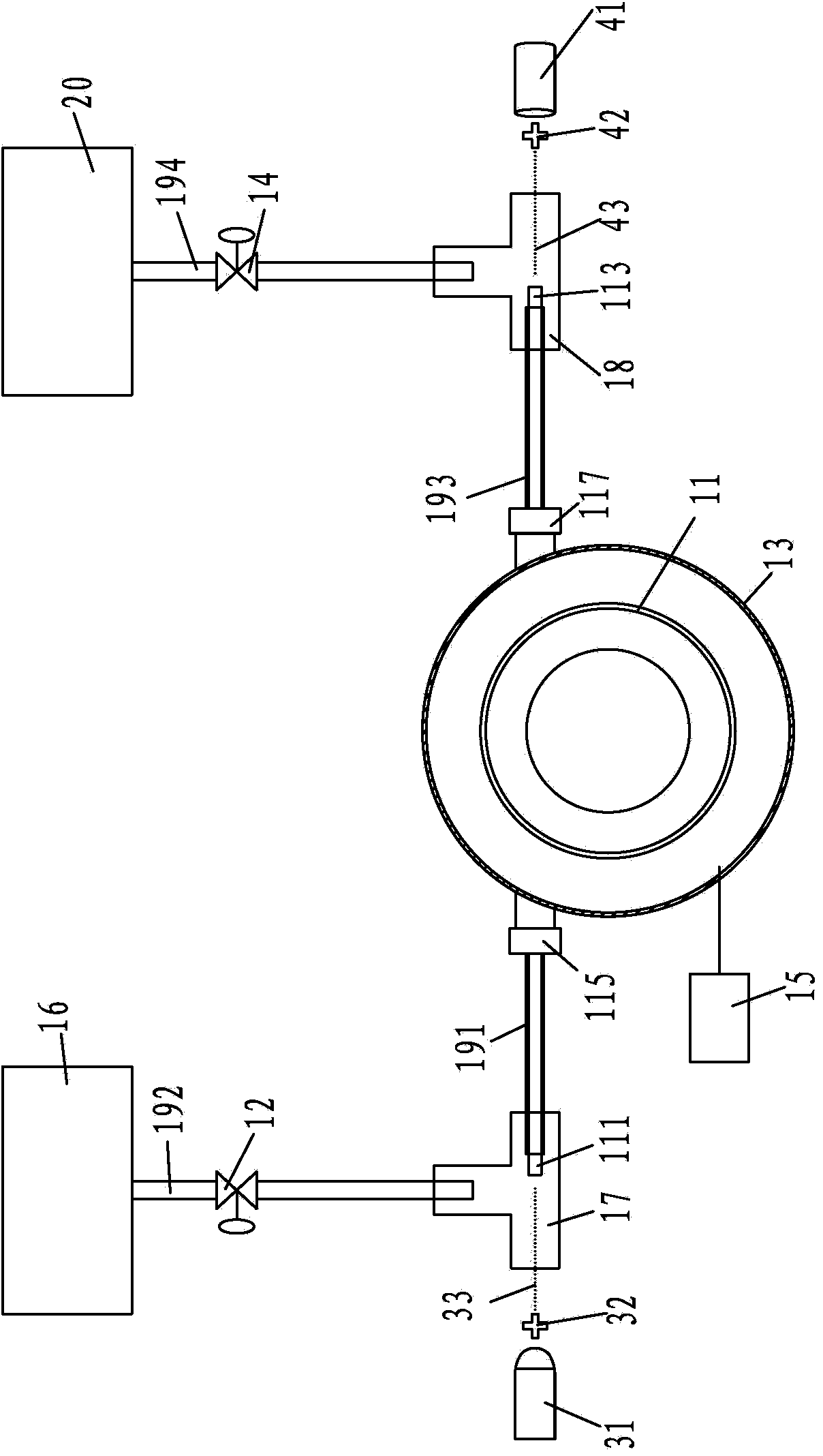
[0008] Such as figure 1 As shown, the negative pressure liquid inlet device based on the liquid core waveguide of the present invention includes a liquid core waveguide 11, a vacuum chamber 13, a vacuum pump 15 and left and right joints 17, 18, the vacuum chamber 13 is a closed cavity, and the vacuum pump 15 and the vacuum The inner cavity of the cavity 13 is connected, the main part of the liquid core waveguide 11 is arranged in the vacuum cavity 13 and the sampling end 111 and the detection end 113 of the liquid core waveguide 11 all protrude out of the vacuum cavity 13, and the liquid core waveguide 11 Connectors 115 and 117 are respectively provided between the main body and the sampling end 111 and the detection end 113. The sampling end 111 of the liquid core waveguide 11 is covered with a first sampling capillary line 191, and the first sampling capillary line 191 is sleeved There is a left joint 17, and the left joint 17 is sleeved with a second sampling capillary line...


PUM


Abstract

The invention provides a negative-pressure liquid feeding device based on a liquid core wave guide pipe. The negative-pressure liquid feeding device comprises a liquid core wave guide pipe, a vacuum chamber, a vacuum pump, a left connector and a right connector, wherein the vacuum pump is communicated with an inner cavity of the vacuum chamber; a main body part of the liquid core wave guide pipe is arranged in the vacuum chamber; a sample feeding end and a detection end of the liquid core wave guide pipe stretch out of the vacuum chamber; the sample feeding end of the liquid core wave guide pipe is sleeved with a first sample feeding capillary pipeline; the first sample feeding capillary pipeline is connected with the left connector; the left connector is connected with a second sample feeding capillary pipeline for connecting a sample position; the second sample feeding capillary pipeline is provided with a left valve; the detection end of the liquid core wave guide pipe is sleeved with a first sample discharging capillary pipeline; the first sample discharging capillary pipeline is connected with the right connector; the right connector is connected with a second sample discharging capillary pipeline for connecting a waste discharging device; the second sample discharging capillary pipeline is provided with a right valve. The negative-pressure liquid feeding device based on the liquid core wave guide pipe can prevent a sample solution from being crossly polluted and has the advantages of small volume, low power consumption, easiness in modularization and small detection result error.

Description

technical field [0001] The present invention relates to a measuring instrument, in particular to a device or instrument for optical testing by optical means. Background technique [0002] Liquid-core waveguides have the characteristics of gas permeability, hydrophobicity, chemical inertness, and lower refractive index than water, and have been widely used in various fields such as absorbance detection, fluorescence detection, Raman spectroscopy, and gas sensors. However, due to its hydrophobicity, the liquid cannot be automatically introduced by capillary action, and external power is required to drive the liquid into the liquid core waveguide during application. At present, pressure-driven technology is mainly used to drive liquid into the liquid core waveguide, such as syringe pumps and gravity-driven systems. The change of the flow rate of the liquid can only be achieved by adjusting the liquid level difference. The operation accuracy is relatively high, and the reproduc...

Claims


Application Information

Patent Timeline
IPC IPC(8): G01N21/01
Inventor 刘霁欣周靖路东
Owner BEIJING JITIAN INSTR CO LTD
Why Eureka
Try Eureka