
Method for quantitatively evaluating each phase structure in hot rolling TRIP (transformation-induced plasticity) steel

A quantitative evaluation and organization technology, applied in measuring devices, instruments, scientific instruments, etc., can solve the problems of difficulty in distinguishing retained austenite and martensite, and inability to distinguish retained austenite and martensite, etc. The effect of reflecting and quantifying the results accurately

Active Publication Date: 2013-12-18
INST OF RES OF IRON & STEEL JIANGSU PROVINCE
View PDF4 Cites 11 Cited by
  • Summary
  • Abstract
  • Description
  • Claims
  • Application Information

AI Technical Summary

Problems solved by technology

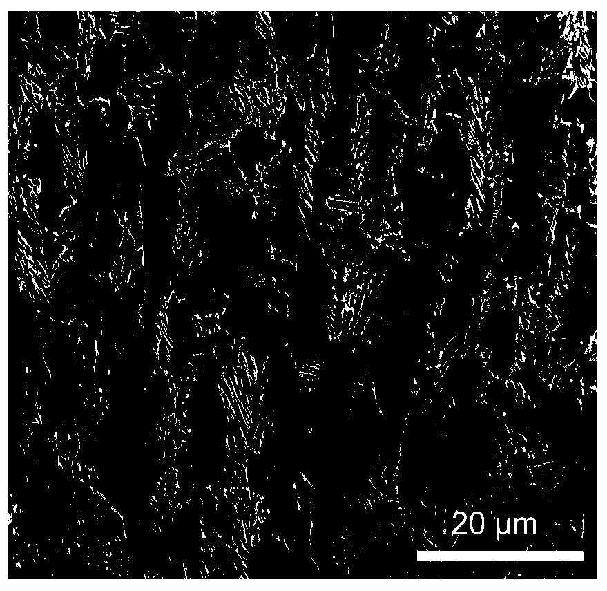
[0003] There are two traditional methods for multi-phase identification of TRIP steel: ① metallographic staining method, this method uses different coloring degrees of different tissues to distinguish, and ferrite and bainite can be distinguished after coloring by this method, but for M In the TRIP steel of Island A, the coloring method cannot directly distinguish the retained austenite from the martensite; ② The large and small angle grain boundaries and the phase formation method of the reverse pole figure, this method first realizes the BCC phase according to the difference in the BCC and FCC phase structures and FCC phase separation, and then use the difference in grain orientation in ferrite and bainite (there are more small-angle grain boundaries in bainite structure, and more large-angle grain boundaries in ferrite structure), to realize ferrite and bainite Separation of tenite, and then using independent calculation software to obtain the content of the three, this method is also difficult to distinguish between retained austenite and martensite

Method used


Image

  • Method for quantitatively evaluating each phase structure in hot rolling TRIP (transformation-induced plasticity) steel
  • Method for quantitatively evaluating each phase structure in hot rolling TRIP (transformation-induced plasticity) steel
  • Method for quantitatively evaluating each phase structure in hot rolling TRIP (transformation-induced plasticity) steel

Examples


Embodiment 1

[0025] 1) Use wire cutting to cut a sample of appropriate size, and use coarse sandpaper to roughly grind the six sides of the sample so that the upper and lower surfaces are parallel, and then finely grind the surface where the data is to be collected on the automatic grinding machine;

[0026] 2) Put the sample on a fully automatic polishing machine for fine mechanical polishing, select a particle size of about 0.02 μm, and polish for about 3 minutes until no obvious scratches can be observed on the surface of the sample under a metallographic microscope at 50 to 100 times, then polish The samples were quickly washed in absolute ethanol and dried with hot air with a hair dryer;

[0027] 3) Carry out rapid and light corrosion on the polished and scratch-free samples, and the degree of corrosion should be such that the grain boundaries can be seen under the optical microscope; the etchant used is: 4% nitric acid alcohol solution;

[0028] 4) Observe the microstructure of the s...


PUM


Abstract

The invention relates to a method for quantitatively evaluating each phase structure in hot rolling TRIP (transformation-induced plasticity) steel. The method comprises the following steps: quantitatively measuring an FCC phase (retained austenite) and a BCC phase (ferrite, bainite and martensite) of the hot rolling TRIP steel by using an electronic backscattered diffraction device arranged on a scanning electron microscope; firstly recognizing the retained austenite according to a distinct difference of the FCC phase and the BCC phase in structure, and then quantitatively distinguishing the three phases by using a gray value difference in a kikuchi band contrast BC (Band Contrast) image in EBSD (electron backscattered diffraction) processing software according to the difference of the three similar structure phases of the ferrite, the bainite and the martensite in kikuchi pattern quality, so as to achieve multi-phase separation and quantitative analysis of the hot rolling TRIP steel. The method is accurate and reliable, and can be applied to the technical field of measurement of tissues in the steel.

Description

technical field [0001] The invention belongs to the technical field of microstructure measurement in steel, and in particular relates to a method of using EBSD (Electron Backscattered Diffraction) technology to distinguish the four phases of ferrite, bainite, martensite and retained austenite in TRIP steel and its Quantitative Analysis Methods. Background technique [0002] TRIP (Transformation Induced Plasticity) steel is transformation induced plasticity steel, through the phase transformation induction effect, the residual austenite in the steel undergoes martensitic transformation under the action of plastic deformation, thereby improving the strength and toughness of the steel. TRIP steels generally contain ferrite, bainite, and austenite structures, and martensite structures still exist after deformation-induced transformation occurs. Austenite belongs to the face-centered cubic structure, and it is easy to distinguish it according to the difference in structure, whil...

Claims


Application Information

Patent Timeline
Patent Type & Authority Applications(China)
IPC IPC(8): G01N23/203
Inventor 牛亚慧张珂洪慧敏金传伟
Owner INST OF RES OF IRON & STEEL JIANGSU PROVINCE
Learn More