Controller redundancy and switching method

A controller and main controller technology, applied in the direction of comprehensive factory control, comprehensive factory control, electrical program control, etc., can solve the problems of system operation influence, high failure rate, complex external circuit design, etc., to achieve maximum flexibility and guarantee Reliability, noise reduction effect

Active Publication Date: 2013-12-18
BEIJING SIFANG JIBAO AUTOMATION +1
View PDF3 Cites 65 Cited by
  • Summary
  • Abstract
  • Description
  • Claims
  • Application Information

AI Technical Summary

Problems solved by technology

[0004] Among the existing controller redundancy switching technologies, there are three implementation methods that are widely used: 1) Multiplex the Ethernet channel between the active and standby controllers and the monitoring system (HMI) to exchange redundant information. The configuration is relatively simple, but the real-time performance of the active/standby switchover is low. Due to the shared network with the HMI, only a small amount of information can be exchanged between the active and standby machines, and the undisturbed switchover cannot be strictly guaranteed; 2) Use a dedicated redundant communication chan

Method used


Image

  • Controller redundancy and switching method
  • Controller redundancy and switching method
  • Controller redundancy and switching method

Examples


Embodiment Construction

[0023] The technical scheme of the present invention will be described in further detail below in conjunction with the accompanying drawings.

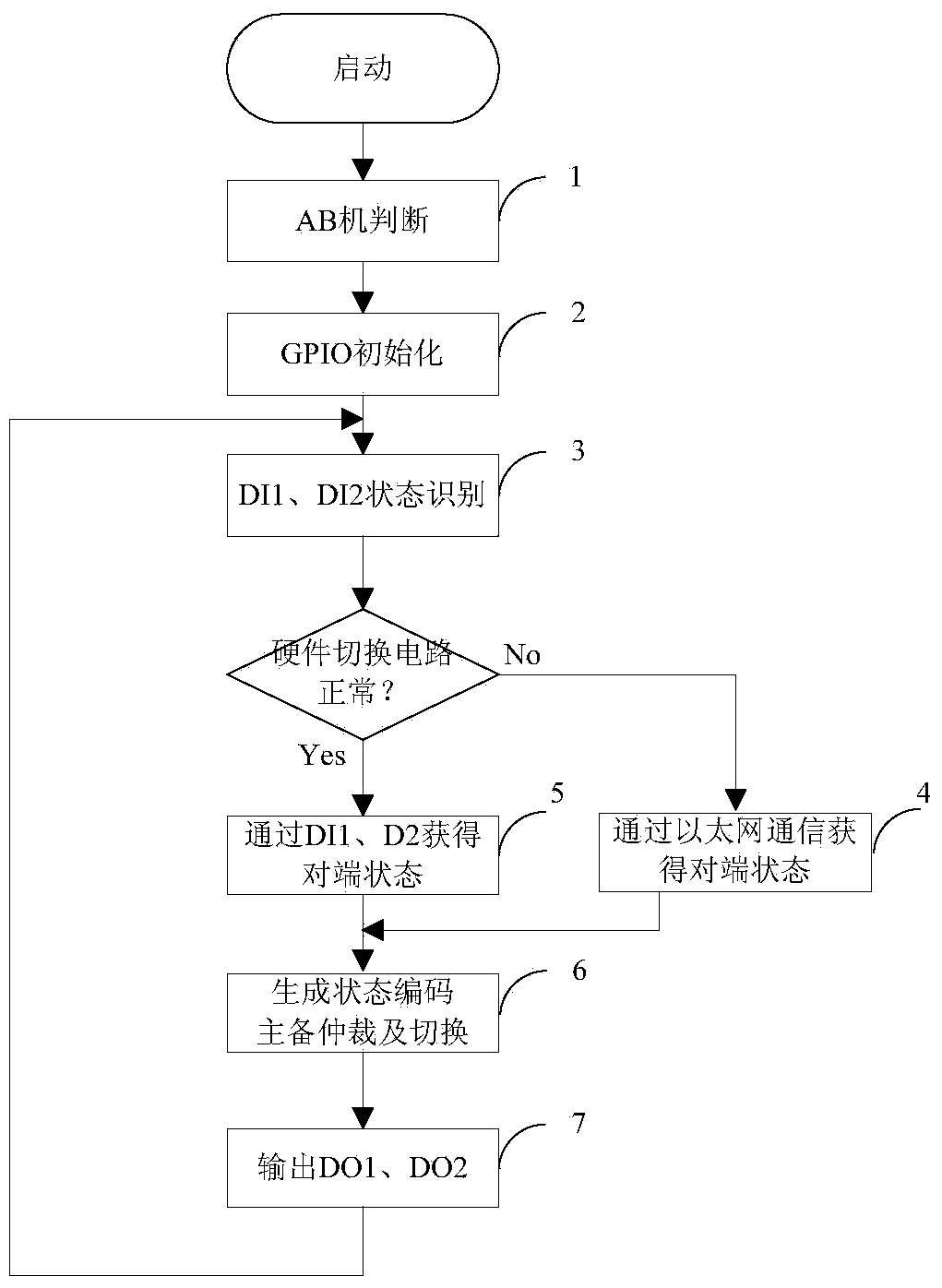
[0024] Such as image 3 As shown, the present invention discloses a controller redundancy and switching method, the method includes the following steps:

[0025] Step 1: The active and standby controllers use exactly the same hardware, and distinguish between controller A and controller B by the physical address of the controller. The odd address is controller A, and the even address is controller B. For the rack installation structure, the physical address is the same as the slot. For the split installation structure, set the physical address according to the DIP switch.

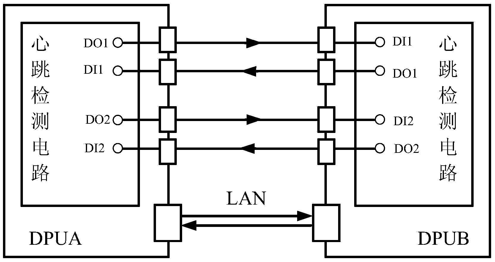
[0026] Step 2: Set up a switching circuit between controller A and controller B, such as figure 1 As shown, the active and standby controllers realize the hardware switching circuit through four general-purpose input and output GPIOs and corresponding peripheral c...


PUM


Abstract

The invention discloses controller redundancy and a switching method. The method is used for the redundancy switching logic between an industrial controller main machine and a spare machine. Calculation and output synchronization between the main machine and the spare machine is guaranteed, and rapid undisturbed switching is achieved when the main machine fails. A switching circuit is composed of two pairs of GPIO control lines and a 100M Ethernet. Through recognition of low level states, pulse signal states and high level states of IOs, the normal state or the failure state of the opposite end controller main machine or the spare machine is obtained, and the normal state or the failure state of the main machine or the spare machine of an opposite end controller can be obtained in a communication mode when the hardware switching circuit fails, so that arbitration and switching of the main machine and the spare machine are achieved. The design method of state machines is adopted, the operation states of the controller are summarized to be five states that the main machine is normal, the main machine fails, the spare machine is normal, the spare machine fails, and opposite ends are powered off, and the arbitration treatment of the main machine and the spare machine is achieved through matrixes of the state machines. The hardware switching circuit and redundant communication serve as connecting signals between redundancy devices, reliability of redundancy switching control is greatly enhanced, and stable operation of an industrial control system can be effectively guaranteed.

Description

technical field [0001] The invention belongs to the technical field of industrial automatic control, and in particular relates to a distributed control system (DCS) controller redundancy and switching method, and is applicable to various industrial automatic control systems with redundant configurations. Background technique [0002] In the field of industrial automatic control, the cost of equipment downtime due to communication failures and equipment failures is extremely expensive. Hot standby redundancy is one of the most effective technologies to improve system reliability, such as power redundancy, controller redundancy, and network redundancy. , server redundancy, etc. [0003] The hot standby redundancy of the controller is composed of two controllers with exactly the same hardware and engineering configuration. The controllers usually switch in two ways: 1) switching hardware circuits through redundancy; 2) exchanging information through redundant communication chan...

Claims


Application Information

Patent Timeline
IPC IPC(8): G05B19/418
CPCY02P90/02
Inventor 杨咏林白雪玲苏亚楠奚志江王晓峰黄磊焦邵华
Owner BEIJING SIFANG JIBAO AUTOMATION
Why Eureka
Try Eureka