A broadband signal phase modulator and its modulation method

A phase modulation, broadband signal technology, applied in the direction of automatic power control, electrical components, multi-carrier systems, etc., can solve the problems of miniaturization of communication terminals, poor connection of modulation frequency bands, increase of filter group delay, etc. question

Inactive Publication Date: 2016-08-31
UNIV OF ELECTRONIC SCI & TECH OF CHINA
View PDF2 Cites 0 Cited by
  • Summary
  • Abstract
  • Description
  • Claims
  • Application Information

AI Technical Summary

Problems solved by technology

[0004] However, the phase modulation method based on the phase-locked loop also has some disadvantages: during the modulation process, precise frequency control of the voltage-controlled oscillator is required to prevent the accumulation of phase errors; the frequency division ratio of the phase-locked loop is extremely high, which reduces the phase noise index of the output signal
In the actual application test, the modulation characteristics of this method have good performance at the low end and high end, but there is a fault in the middle section, that is, it cannot be well connected in the entire modulation frequency band.
For another example, a digital predistortion filter can be used to linearly compensate the loop filter. However, the added predistorter will increase the size and weight of the circuit, which is not conducive to the miniaturization of modern communication te

Method used


Image

  • A broadband signal phase modulator and its modulation method
  • A broadband signal phase modulator and its modulation method
  • A broadband signal phase modulator and its modulation method

Examples


Embodiment Construction

[0036] Hereinafter, the present invention will be specifically described with reference to the drawings of embodiments of the present invention.

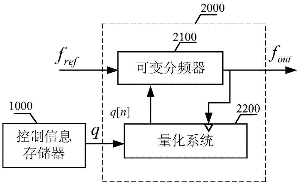
[0037] Such as figure 1 As shown, the broadband signal phase modulator applied to the polar coordinate transmission system includes a control information memory 1000 and a direct digital frequency synthesizer 2000 . The direct digital frequency synthesizer 2000 is composed of a variable frequency divider 2100 and a quantization system 2200 . The circuit is realized by FPGA, and the 16QPSK baseband signal is loaded as the phase modulation signal, and the reference signal frequency is f ref is 10GHz, the frequency division value changes between 4 and 5, and the output frequency f out The range is 2-2.5GHz.

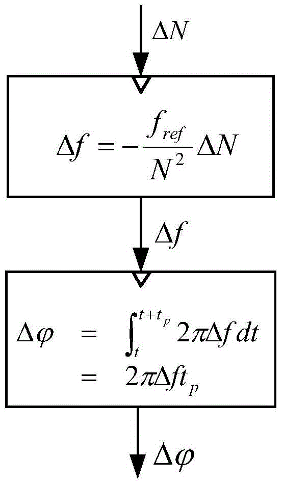
[0038] Such as figure 2As shown, it is the phase modulation flow chart of the present invention, which is the core content of the present invention, and embodies the basic principle of the phase modulation method. Based on th...


PUM


Abstract

The invention provides a broadband signal phase modulator and a modulation method applied to a polar coordinate transmitter, including two parts of a control information memory and a direct digital frequency synthesizer. The output end of the control information memory is connected to the control end of the direct digital frequency synthesizer, and the phase modulation is realized by controlling the frequency division parameters. The direct digital frequency synthesizer synthesizes the fractional frequency division signal based on the idea of ​​time averaging, and consists of a variable frequency divider and a quantization system. The output terminal of the quantization system is connected to the frequency division control terminal of the variable frequency divider to realize the adjustable frequency division value. The output end of the variable frequency divider is connected to the clock control end of the quantization system to ensure that the instantaneous frequency of the output signal of the quantization system will only change at the zero crossing point. The quantization system uses an efficient quantization method to reduce fractional spurs introduced by direct digital frequency synthesizers. Since the present invention is implemented using an open loop structure, the bandwidth of the phase modulation signal is not limited by the loop.

Description

technical field [0001] The technology relates to the field of wireless communication technology, in particular to the phase modulation technology of a coordinate transmitter. By using an open-loop phase modulation structure, the bandwidth of the phase-modulated signal is not limited by the system loop. Background technique [0002] Compared with the traditional Cartesian transmitter using I / Q quadrature modulation, the polar coordinate transmitter evolved from the EER transmitter has received a lot of in-depth research due to its advantages of high efficiency and easy integration. The polar coordinate transmitter is different from the rectangular coordinate transmitter. It needs to convert the I / Q rectangular coordinate information into polar coordinate ρ / θ information and then amplify them separately, and finally combine them into a rectangular coordinate modulation signal for transmission. Therefore, the amplitude and phase of the transmitted signal Information separation...

Claims


Application Information

Patent Timeline
IPC IPC(8): H03L7/18H04L27/36
Inventor 游飞张渤海童仁彬和谦何松柏
Owner UNIV OF ELECTRONIC SCI & TECH OF CHINA
Why Eureka
Try Eureka