A screw automatic cleaner

An automatic cleaning and screw technology, applied in cleaning methods and utensils, chemical instruments and methods, cleaning methods using tools, etc., can solve problems such as increased work intensity, rapid consumption of wire wheels, and reduced local hardness of the screw, reducing labor The effect of strength, improving work efficiency, and speeding up the melting time

Active Publication Date: 2015-09-30
TIANJIN KINGFA NEW MATERIAL +1
View PDF6 Cites 0 Cited by
  • Summary
  • Abstract
  • Description
  • Claims
  • Application Information

AI Technical Summary

Problems solved by technology

[0004] The above are the methods currently in use or existing, which can achieve the function of cleaning, but there are the following disadvantages: Method 1. The special material is expensive and used for one-time use, so the cost is high; and after the screw is cleaned, it needs to be cleaned at the production site. Clean up used washing materials, which not only increases work intensity, but also risks contamination on site
Method 2. In the cold state of the screw at room temperature, it is difficult to tap the attached plastic shovel, it takes a long time, the labor intensity is high, and the screw is easy to be damaged
At the same time, the wire wheel used for cleaning is consumed quickly and needs to be replaced frequently, which will increase the cleaning cost
Method 3. Working with open flames with hand-held tools has a high safety risk; when the attachments are burned, the smoke and other pollution are relatively large, which is likely to affect human health; it is also easy to reduce the local hardness of the screw due to uneven heating; and the consumption of liquefaction The gas consumption is large, which increases the cleaning cost
Method 4. The heating of the oil tank needs to maintain the oil temperature in the oil tank for a long time, so that the energy consumption is very large, and when dealing with long screws (the extruder screw can generally reach 2.5 meters and above), a large oil tank is required, so the energy consumption is greater and less expensive. Safe, but it is inconvenient to clean up if the attachment falls in the oil tank

Method used


Image

  • A screw automatic cleaner
  • A screw automatic cleaner
  • A screw automatic cleaner

Examples


Embodiment Construction

[0029] The present invention will be further described below with reference to the accompanying drawings and embodiments.

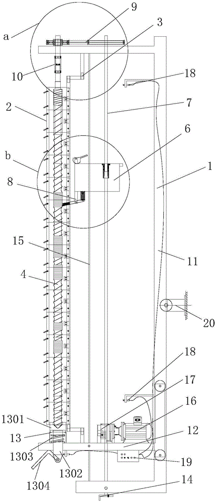
[0030] like Figure 1 to Figure 3 A screw automatic cleaner shown includes a cleaning frame 1 for clamping the screw, a heating ring 2 and a rotating bracket 3, and the heating ring 2 is installed on the cleaning frame 1 through the rotating bracket 3; when the screw 4 is clamped When cleaning the rack 1 , the heating ring 2 is passed through by the screw 4 , and the heating ring 2 covers the entire threaded portion of the screw 4 . Specifically, the heating coil 2 is formed by sequentially connecting multiple heating coil units, so that the length of the heating coil 2 can be adjusted according to the length of the screw.

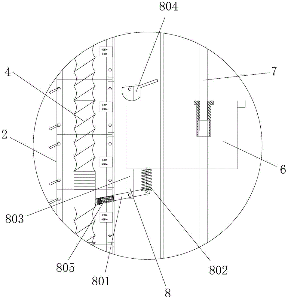
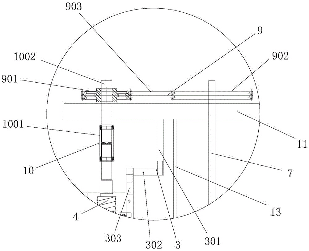
[0031] like Figure 4 and Figure 5 As shown, the heating ring 2 includes two main bodies 201 with a semicircular section, and the two main bodies 201 are connected by bolts 5; the rotating bracket 3 includes a fixed rod I301, a ro...


PUM


Abstract

The invention discloses an automatic screw rod cleaning device, which comprises a cleaning frame, a heating ring and a rotating support frame, wherein the cleaning frame is used for installing and clamping a screw rod, and the heating ring is arranged on the cleaning frame through a rotating mechanism, when the screw rod is clamped and installed onto the cleaning frame, the heating ring is penetrated by the screw rod, and in addition, the heating ring covers the screw thread part of the whole screw rod. The heating ring in the automatic screw rod cleaning device covers the screw thread part of the whole screw rod, the circumference surface of the whole screw rod can be heated, the occurrence of a hardness reduction condition caused by local heating of the screw rod can be avoided, meanwhile, the surface of the screw rod can be fast heated, the melting time of attachment is shortened, and the work efficiency is greatly improved.

Description

technical field [0001] The invention relates to cleaning equipment, in particular to a screw automatic cleaner. Background technique [0002] In the plastics industry, extruders and injection molding machines are widely used. These devices modify or shape plastics through the compression, conveying, shearing and other functions of the screw. When changing the material, the former material will stick to the screw, and the screw needs to be cleaned to avoid contamination of the product. [0003] At present, there are several ways to clean the screw: 1. Rinse with special washing machine material; 2. Use an angle grinder to install a steel wire wheel to grind after preliminary scraping with metal tools; 3. Burn manually with a blowtorch such as liquefied gas. ; 4. Use the oil tank heating method to clean the screw device. [0004] The above are the methods currently in use or existing, which can achieve the function of cleaning, but there are the following disadvantages: Met...

Claims


Application Information

Patent Timeline
Patent Type & Authority Patents(China)
IPC IPC(8): B08B7/00B08B1/02B08B13/00
Inventor 刘炜李东陈智敏张智宋晓东王海蛟陶四平
Owner TIANJIN KINGFA NEW MATERIAL
Why Eureka
Try Eureka