
Illumination device and usage method of deep ultraviolet projection lithography machine

A lighting device and lithography machine technology, applied in the field of micro-lithography, can solve the problems of reducing scanning speed and scanning range, and achieve the effects of reducing cost and complexity, reducing optical components, and improving light energy utilization

Active Publication Date: 2015-09-16
BEIJING GUOWANG OPTICAL TECH CO LTD
View PDF5 Cites 0 Cited by
  • Summary
  • Abstract
  • Description
  • Claims
  • Application Information

AI Technical Summary

Problems solved by technology

This patent uses the method of cutting the angle spectrum to replace the existing slit scanning, which has the advantages of reducing the scanning speed and scanning range, and no longer needs expensive lighting mirrors, which reduces the cost, but requires a higher Scan Speed ​​Accuracy and Position Accuracy

Method used


Image

  • Illumination device and usage method of deep ultraviolet projection lithography machine
  • Illumination device and usage method of deep ultraviolet projection lithography machine
  • Illumination device and usage method of deep ultraviolet projection lithography machine

Examples


Embodiment Construction

[0041] Below, the present invention will be described in detail in conjunction with the accompanying drawings and preferred embodiments.

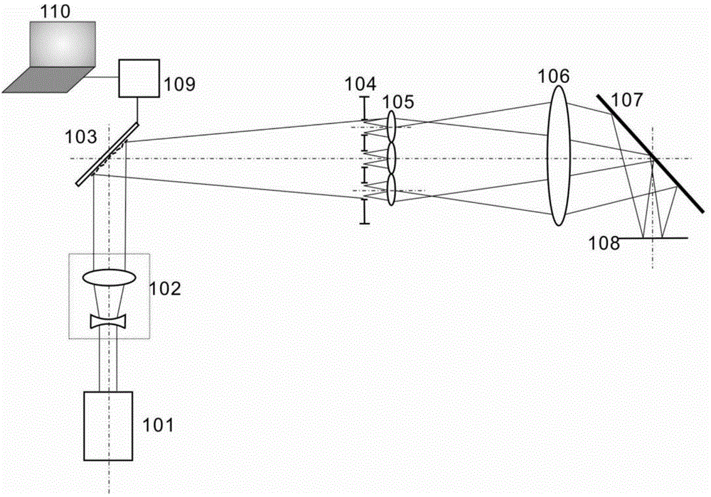
[0042] see first image 3 , Figure 4 , image 3 It is a schematic structural diagram of an embodiment of the illumination device of the deep ultraviolet projection lithography machine of the present invention. Figure 4 It is a schematic diagram of an embodiment of using an aperture array in the present invention. Depend on image 3 It can be seen that the lighting device of the projection lithography machine of the present invention includes: a laser source 101, which is composed of a beam expander 102, a micromirror array 103, an aperture array 104, a microlens array 105, Illumination mirror group 106 and reflector 107, described micromirror array 103 has control system, and this control system comprises computer 110 and microreflector array controller 109, and described computer 110 is controlled by microreflector array controller 1...


PUM


Abstract

The invention provides an illumination device of a deep ultraviolet projection mask aligner and an application method. The device comprises a laser source; a beam expander, a micro-mirror array, a diaphragm array, a micro-lens array, an illumination mirror set and a reflecting mirror are arranged in sequence along an output beam of the laser source, wherein a control system of the micro-mirror array comprises a computer and a micro- mirror array controller; the computer controls each micro-mirror unit on the micro-mirror array to do two-dimensional rotation by the micro-mirror array controller, so that a strength mode needed by photoetching on the diaphragm array can be formed by an expanded beam via the micro-mirror array; after the strength mode is formed, the computer controls the micro-mirror array to do one-dimensional rotation by the micro-mirror array controller, so that the formed strength mode moves relative to the diaphragm array, so as to finish a photoetching scanning process. According to the illumination device of the deep ultraviolet projection mask aligner and the application method, the structure is simplified greatly, and the stability and the optical energy utilization rate of the system are improved.

Description

technical field [0001] The invention belongs to the field of microlithography, and relates to projection lithography technology, in particular to an illuminating device and a usage method of a deep ultraviolet projection lithography machine. Background technique [0002] Photolithography is used to manufacture large-scale integrated circuits, micro-electromechanical systems, etc. The projection lithography machine mainly includes an illumination system and a projection objective lens. The illumination system uniformly illuminates the reticle, and the fine patterns on the reticle are imaged by the projection objective lens onto the silicon wafer coated with photoresist. The illumination system in the projection lithography machine mainly realizes the shaping of the laser beam, uniform illumination, change of coherence factor, polarization control, field of view control, etc. [0003] Commonly used projection lithography lighting systems such as figure 1 shown. The light be...

Claims


Application Information

Patent Timeline
Patent Type & Authority Patents(China)
IPC IPC(8): G03F7/20
Inventor 张运波曾爱军王莹黄惠杰
Owner BEIJING GUOWANG OPTICAL TECH CO LTD
Features
  • Generate Ideas
  • Intellectual Property
  • Life Sciences
  • Materials
  • Tech Scout
  • Unparalleled Data Quality
  • Higher Quality Content
  • 60% Fewer Hallucinations
Learn More