Self-powered magneto-rheological damper

A variable damper and electromagnetic flow technology, applied in the field of magnetorheological vibration reduction, can solve the problems of limited impeller speed, low energy conversion efficiency, poor energy conversion effect, etc., and achieve the goal of improving conversion efficiency and energy conversion efficiency Effect

Active Publication Date: 2014-01-01
太仓久庄管业有限公司
View PDF7 Cites 21 Cited by
  • Summary
  • Abstract
  • Description
  • Claims
  • Application Information

AI Technical Summary

Problems solved by technology

[0003] In practical application, the magneto-rheological damper needs external power supply, and the lead wire used to connect with the external power supply in the magneto-rheological damper will cause certain damage to the sealing structure of the magnetorheological damper, so there is leakage. At the same time, the external wires are also vulnerable to environmental corrosion and rat bites, resulting in breakage, resulting in failure or interruption of the external power supply of the magnetorheological damper, resulting in deterioration of the vibration reduction performance of the magnetorheological damper. poor or uncontrollable
[0004] In view of this problem, some scholars have provided a magneto-rheological damper with a "self-powered" structure. The principle of self-power supply is: the electromagnetic principle is used inside the magnetorheological damper to generate electric energy for the excitation coil of the magnetorheological damper. , for example: Chinese Invention Patent Application Publication No. 200910103744 discloses "a self-powered electromagnetic rheological damper" in its description, which converts the scouring of the blades by the magneto-rheological fluid into the rotation of the butterfly rotor, thereby changing the The magnetic flux of the butterfly rotor coil realizes the conversion of mechanical energy into electrical energy, but the processing of the impeller of this structure is complicated, and at the same time, the speed of the impeller is limited due to factors such as centrifugal force and flow loss, resulting in low energy conversion efficiency.
Another example: the Chinese invention patent application with publication number 102278411 discloses "a self-supplied electromagnetic rheological damper and its vibration damping system" in its specification, which is based on the traditional double-extended rod magnetorheological damper. Above, the piston rod is connected to the permanent magnet through the connecting rod, and the permanent magnet acts as a mover to move with the piston rod. The speed of the permanent magnet in this structure can only be the same as the speed of the piston rod, and the energy conversion effect is not good under the low-speed movement of the piston rod.

Method used


Image

  • Self-powered magneto-rheological damper
  • Self-powered magneto-rheological damper
  • Self-powered magneto-rheological damper

Examples


Embodiment Construction

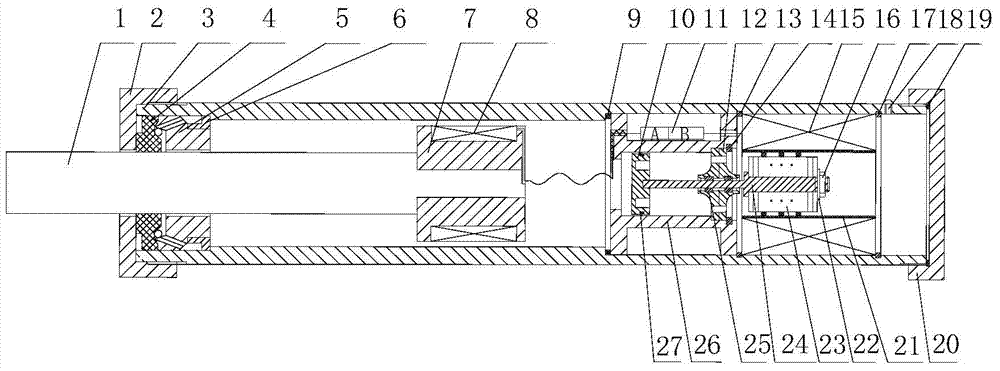
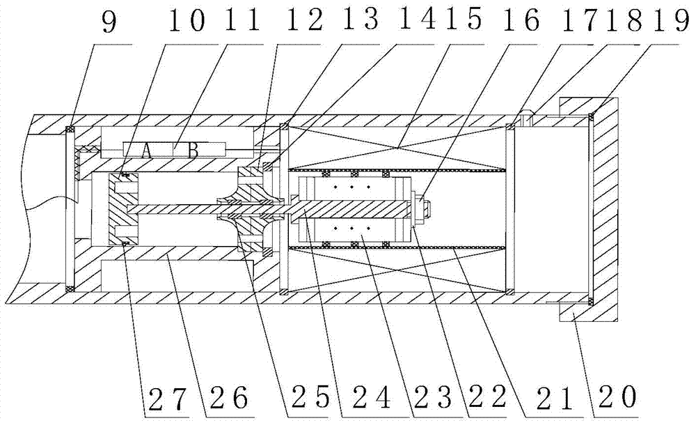
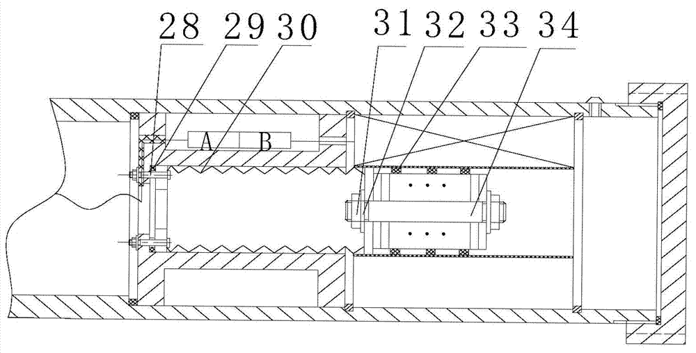
[0021] figure 1 It is a structural schematic diagram of an embodiment of the self-powered electromagnetic rheological damper provided by the present invention, figure 2 It is a structural schematic diagram of an embodiment of the self-powered part using floating piston compensation provided by the present invention, image 3 It is a structural schematic diagram of an embodiment of the self-powered part that adopts bellows compensation provided by the present invention.

[0022] Combine below Figures 1 to 3 , to describe the embodiment of the present invention.

[0023] Such as figure 1 As shown, the self-powered electromagnetic rheological shock absorber of this embodiment mainly includes: a cylinder 3 .

[0024] Wherein, the two ends of the cylinder 3 are respectively sealed by the upper end cap 2 and the lower end cap 20. In this embodiment, the thread connection between the cylinder 3 and the upper and lower end caps 2, 20 is mainly sealed, and of course other Sealin...


PUM


Abstract

The invention discloses a self-powered magneto-rheological damper which has the advantages of being high in energy exchange efficiency, easy to manufacture, and the like. The self-powered magneto-rheological damper mainly comprises a cylinder barrel, a locating barrel, a compensation unit, a hollow coil and a permanent magnet. The locating barrel is arranged in the cylinder barrel and divides the cylinder barrel into a locating barrel upper cavity and a locating barrel lower cavity, the locating barrel upper cavity is filled with magneto-rheological liquid, and a piston, a piston rod and an energizing coil are arranged in the locating barrel upper cavity. The locating barrel lower cavity is filled with compensation gases, the compensation unit is arranged in the locating barrel, the hollow coil is arranged in the locating barrel lower cavity, and the permanent magnet is arranged in an inner cavity of the hollow coil and is fixedly connected with the compensation unit. When the piston does reciprocating movement, the compensation unit drives the permanent magnet to move in a reciprocating mode in the inner cavity of the hollow coil, and therefore mechanical energy is converted to electric energy.

Description

technical field [0001] The invention relates to the technical field of magnetorheological damping, in particular to a self-powered electromagnetic rheological damper. Background technique [0002] Since the magnetorheological damper can use the magnetorheological fluid to quickly realize the reversible rheological characteristics of the liquid and the solid under the action of a magnetic field, it can realize a continuously adjustable and controllable damping force, and has low energy consumption, wide dynamic response range and responsiveness. Therefore, magnetorheological dampers have gradually replaced traditional hydraulic and servo-structure dampers, and are widely used in civil structures, automobile suspensions, automobile bumpers, and automobile seats. [0003] In practical application, the magneto-rheological damper needs external power supply, and the lead wire used to connect with the external power supply in the magneto-rheological damper will cause certain damag...

Claims


Application Information

Patent Timeline
Patent Type & Authority Applications(China)
IPC IPC(8): F16F9/53
Inventor 董小闵于建强古晓科王小龙
Owner 太仓久庄管业有限公司
Why Eureka
Try Eureka