

Quantum dot film and backlight module
A technology of quantum dots and quantum dot layers, applied in the field of quantum dots, can solve the problems of short service life of quantum dots, increased cost, high temperature of LED chips, etc., and achieve the effect of improving light conversion efficiency, improving utilization rate, and reducing thickness
- Summary
- Abstract
- Description
- Claims
- Application Information
AI Technical Summary
Problems solved by technology
Method used
Image


Examples
Embodiment approach 1
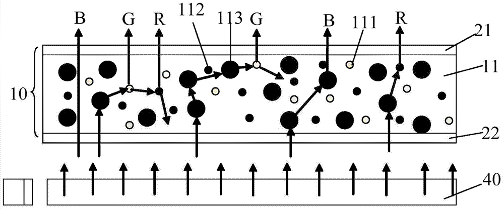
[0058] ginseng figure 1 Shown, a kind of quantum dot thin film comprises:
[0059] The quantum dot layer 10 , the quantum dot layer 10 includes a matrix 11 and a number of quantum dots uniformly dispersed in the matrix 11 , the quantum dots in this embodiment include red quantum dots 111 and green quantum dots 112 . The matrix 11 also includes a number of uniformly dispersed diffusion particles 113, the diffusion particles 113 are used to scatter the incident light in the matrix and increase the optical path of the light passing through the quantum dot layer;
[0060] The water vapor barrier layers on both sides of the quantum dot layer 10 include a first water vapor barrier layer 21 above the quantum dot layer 10 and a second water vapor barrier layer 22 below the quantum dot layer 10 . The moisture vapor barrier is a solid material, or a cured liquid, gel, polymer.
[0061] In this embodiment, the material of the matrix 11 is acrylate resin, organosiloxane resin, acrylate-...
Embodiment approach 2
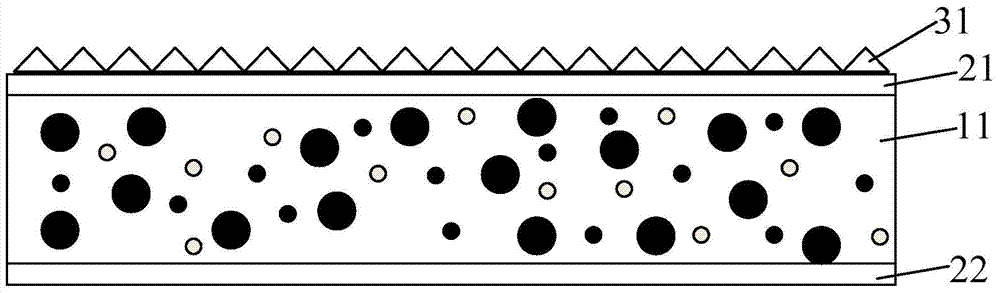
[0076] Such as image 3 As shown, a first microstructure 31 is provided on the surface of the first water vapor barrier layer 21. In this embodiment, the first microstructure is an isosceles triangle. In other embodiments, the microstructure may also include isosceles triangle, polygon A combination of one or more of conical, conical, hemispherical, and irregular shapes with raised structures on the surface.
[0077] The quantum dot layer and the water vapor barrier layer in this embodiment are the same as those in Embodiment 1, and will not be repeated here.
Embodiment approach 3
[0079] Such as Figure 4 As shown, a first microstructure 31 and a second microstructure 32 are respectively provided on the surfaces of the first water vapor barrier layer 21 and the second water vapor barrier layer 22. In this embodiment, the first microstructure and the second microstructure are hemispherical In other embodiments, the microstructure can also be a combination of one or more of the microstructures including isosceles triangle, polygonal cone, cone, hemisphere, and irregular shapes with raised structures on the surface.
[0080] The quantum dot layer and the water vapor barrier layer in this embodiment are the same as those in Embodiment 1, and will not be repeated here.
[0081] Correspondingly, the backlight module in another embodiment of the present invention includes: a light source, a light guide plate, a prism sheet, and a quantum dot film, wherein the quantum dot film is located anywhere above the light guide plate and below the prism sheet. The quant...
PUM
| Property | Measurement | Unit |
|---|---|---|
| Diameter | aaaaa | aaaaa |
| Diameter | aaaaa | aaaaa |
| Diameter | aaaaa | aaaaa |
Abstract
Description
Claims
Application Information