
Method for processing high-speed generator rotor core assembly

A technology for high-speed generators and rotor cores, which is applied to electric components, manufacturing motor generators, electrical components, etc., and can solve problems affecting the normal operation of high-speed generators, punching of rotor core components and cracking and damage of damping copper strips , to achieve the effect of reducing eddy current loss and improving insulation performance

Active Publication Date: 2014-01-01
SHAANXI AVIATION ELECTRICAL
View PDF5 Cites 8 Cited by
  • Summary
  • Abstract
  • Description
  • Claims
  • Application Information

AI Technical Summary

Problems solved by technology

And because when the iron core punching piece is welded by electron beam at the pole piece of the iron core, a weld seam of about 2mm is formed on the side of the iron core pole shoe punching piece. Although the iron core punching piece is formed into an integral core assembly, the weld Existence and welding stress make the iron core punching sheet form a weak link at the welding place. When the strength of the weak point is lower than the external force formed by high-speed rotation, when the rotor assembly rotates at high speed, the rotor iron core assembly punching sheet and damping copper strip will be damaged. Fracture and damage, affecting the normal operation of the high-speed generator

Method used


Image

  • Method for processing high-speed generator rotor core assembly
  • Method for processing high-speed generator rotor core assembly

Examples


specific Embodiment

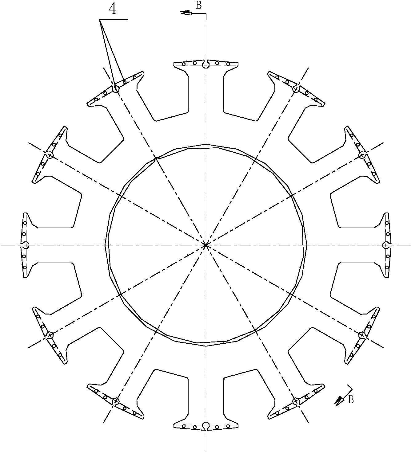
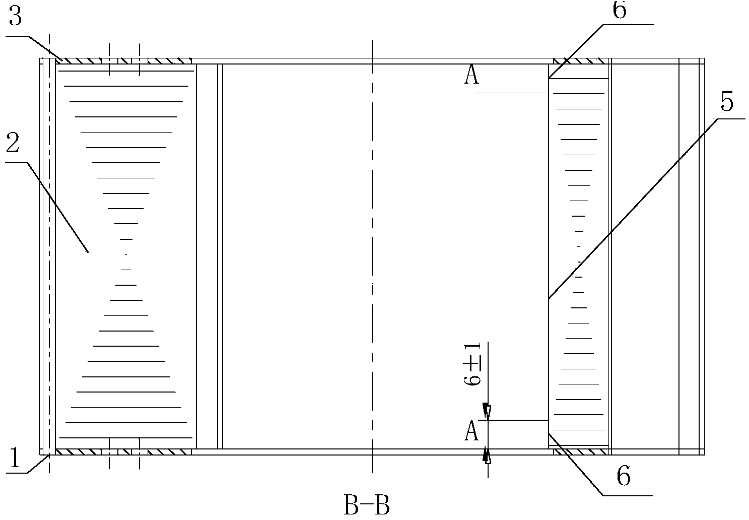
[0035] Step 1: Before the lamination of the rotor sheet 2, use CBP-I adhesive to spray the iron core sheet on one side, and preheat it at 65±2°C for 15 minutes to form a solid adhesive film on the surface of the 2 before lamination ;

[0036] Step 2: Retain 15-20 pieces of rotor punches with a thickness of 0.35mm on both sides of the rotor core. Glue coating process is adopted: that is, no adhesive is applied to the pole body and pole shoe parts, and glue is applied to the rest of the parts. Preheat at 65±2°C for 15 minutes to form a solid film on the surface of 2 before lamination;

[0037] Step 3: On the rotor core assembly stacking jig, stack in the order of rotor copper end plate 3→glue-coated punch 6→glue-spray punch 5→glue-coated punch 6→rotor copper end plate 3, and press on-board pressurization;

[0038] Step 4: Take out the rotor core assembly, install the damping copper strip and weld it;

[0039] Step 5: After the welding is completed, bake and cure according to ...


PUM


Abstract

The invention relates to a method for processing a high-speed generator rotor core assembly. A liquid state adhesion agent which can form a solid state adhesive film before solidification is adopted, therefore, a thin layer adhesive film can be formed by conducting good infiltration on the surface of stamped steel, and a copper damper bar can be protected against contamination in follow-up processing. The method that local gluing is conducted on each piece of iron core stamped steel within the range of 6+ / -1 mm apart from a copper end plate is adopted, therefore, the segments of the copper damper bar and the copper end plate are not affected, and adhesive bonding between pieces of iron core stamped steel can be ensured. The method for processing the high-speed generator rotor core assembly has the advantages that the adhesion agent is used for adhesive bonding so that the overall strength of the rotor core assembly can be improved and the damage, caused by welding, to the iron core stamped steel is overcome; the method that local gluing is conducted on each piece of end stamped steel is adopted so that the welding between the copper damper bar and the copper can not be affected; the adhesion agent is used for adhesive bonding between all the pieces of iron core stamped steel, therefore, the insulating property of all the pieces of stamped steel of a rotor core can be improved, and eddy-current loss of the rotor core assembly can be reduced.

Description

technical field [0001] The invention belongs to a processing method of a motor rotor iron core assembly, and relates to a processing method of a high-speed generator rotor iron core assembly. Background technique [0002] With the development of aviation power system technology, the capacity demand of aviation generators will become larger and larger. Due to the particularity of the application field of aero-motor products, the aero-generator is required to have lighter weight and high power density. Therefore, the requirements for the speed of aero-generators are getting higher and higher, and the speed of some generators exceeds 24000r / min. As for the rotor core with salient pole structure in the generator main rotor, when the main rotor is working, the main rotor core, field winding and slot wedges will generate huge centrifugal force on the slot wedges and the main rotor pole shoes. , the pole shoes of the main generator rotor will generate a lot of internal stress loc...

Claims


Application Information

Patent Timeline
Patent Type & Authority Applications(China)
IPC IPC(8): H02K15/02H02K15/12
Inventor 淡宏斌李昂武雪宁程伟王润辰
Owner SHAANXI AVIATION ELECTRICAL
Learn More