Steel structure combined column system and connecting method thereof
A connection method and technology of combining columns, applied in the directions of columns, piers, pillars, etc., can solve the problems of slow speed, high requirements for hoisting, installation and connection, and low efficiency, and achieve the effects of high efficiency, fast construction progress and high seismic performance.
- Summary
- Abstract
- Description
- Claims
- Application Information
AI Technical Summary
Problems solved by technology
Method used
Image

Examples
Embodiment 1
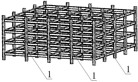
[0045] Such as figure 1 As shown, the steel structure composite column system is composed of a plurality of steel structure composite columns 1, and the steel structure composite columns 1 are connected to each other by bolts to form a whole. Compared with the reinforced concrete building skeleton, the overall skeleton formed by the steel structure composite column system has the advantages of fast construction speed, high seismic performance, no sewage and dust, and reusable materials.
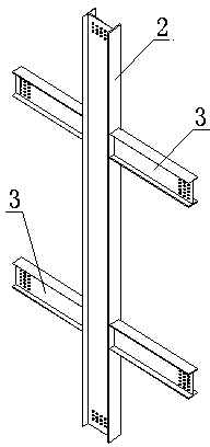
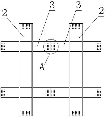
[0046] Such as figure 2As shown, the steel structure composite column 1 is composed of a column 2 and a beam 3, and beams 3 are installed on both sides of the column 2, and the beam 3 is installed symmetrically or misplaced on both sides of the column 2, and the beam 3 is welded or bolted The way of connection is fixedly installed on the column 2. The column 2 is made of I-shaped steel, which is in the shape of "I", and the upper and lower ends of the column 2 are provided with bolt holes ...
Embodiment 2
[0058] The steel structure composite column system is composed of a plurality of steel structure composite columns 1, and the steel structure composite columns 1 are connected to each other by bolts to form a whole. It is characterized in that: Figure 7 As shown, the steel structure composite column 1 is composed of a column 2 and a beam 3. Beams 3 are installed on the front, rear, left, and right sides of the column 2. The beams 3 are symmetrically installed on the column 2 by welding or bolting. The column 2 is made of a rectangular steel pipe, and the upper and lower ends of the column 2 are provided with bolt holes for connection. The beam 3 is also made of rectangular steel pipes, one end of the beam 3 is fixed on the column 2 by welding, and the other end of the beam 3 is provided with bolt holes for connection. The beam 3 has two layers, and is fixed on the column 2 in a flat layer manner. Of course, the beam 3 can also be designed as a single layer or multi-layer, ar...
Embodiment 3
[0062] The steel structure composite column system is composed of a plurality of steel structure composite columns 1, and the steel structure composite columns 1 are connected to each other by bolts up, down, left, and right to form a whole. Such as Figure 8 As shown, it is characterized in that: the steel structure composite column 1 is composed of a column 2 and a beam 3, and beams 3 are installed on three sides of the column 2, and the beam 3 is installed on the column 2 by welding. The column 2 is made of T-shaped steel, and the upper and lower ends of the column 2 are provided with bolt holes for connection. The beam 3 is made of a rectangular tube, one end of the beam 3 is fixed on the column 2 by welding, the other end of the beam 3 is provided with a flange 7 for connection, and the flange 7 is provided with a bolt hole. Of course, in practical applications, the flange 7 may not be used at the other end of the beam 3, and the connection is directly connected by weldi...
PUM
 Abstract
Description
Claims
Application Information
 - R&D
- Intellectual Property
- Life Sciences
- Materials
- Tech Scout
- Unparalleled Data Quality
- Higher Quality Content
- 60% Fewer Hallucinations
Browse by: Latest US Patents, China's latest patents, Technical Efficacy Thesaurus, Application Domain, Technology Topic, Popular Technical Reports.
© 2025 PatSnap. All rights reserved.Legal|Privacy policy|Modern Slavery Act Transparency Statement|Sitemap|About US| Contact US: help@patsnap.com