Laser marking equipment for silicon-based thin-film solar cell

A solar cell and laser scribing technology, applied in laser welding equipment, welding equipment, metal processing equipment, etc., can solve the problem that laser scribing equipment cannot take into account the cost and scribing complex graphics at the same time, affecting the electrical performance of solar cells, etc. Achieve the effect of avoiding being affected by the external environment, reducing equipment costs, and reducing maintenance frequency

Active Publication Date: 2014-01-22
SHEN ZHEN TRONY SCI & TECH DEV CO LTD
View PDF7 Cites 9 Cited by
  • Summary
  • Abstract
  • Description
  • Claims
  • Application Information

AI Technical Summary

Problems solved by technology

[0005] The invention solves the technical problem that the existing laser scribing equipment cannot simultaneously take into account the cost and scribing complex graphics, and at the same time overcomes the problems that the traditional laser scribing equipment produces some particles with smaller diameters during operation, which affects the electrical performance of solar cells, etc.

Method used


Image

  • Laser marking equipment for silicon-based thin-film solar cell
  • Laser marking equipment for silicon-based thin-film solar cell
  • Laser marking equipment for silicon-based thin-film solar cell

Examples


Embodiment 1

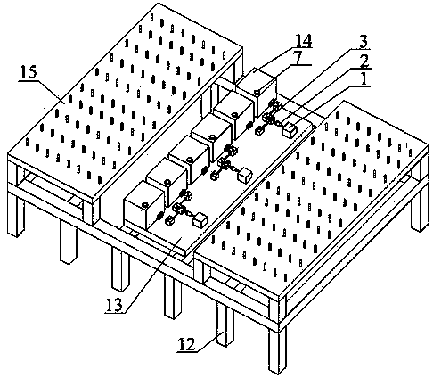
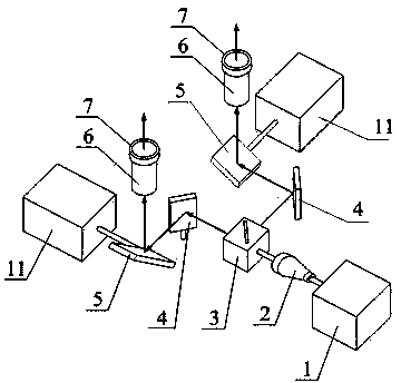
[0027] See figure 1 and figure 2 The laser scribing equipment of this embodiment includes a laser 1, a beam expander 2, a beam splitter 3, a Z-axis galvanometer 4, an X-axis galvanometer 5, a focusing mirror 6, and a protective mirror 7. A beam of laser light emitted by the laser 1 passes through After the beam expander 2, the beam splitter 3 divides the refracted light in the X-axis and the reflected light in the Y-axis. The refracted light is polarized by the Z-axis galvanometer 4 and then passes through the X-axis galvanometer 5, so that the laser goes upward and then passes through the focusing mirror 6 Arrive at the surface of the film layer of the substrate for marking, and at the same time another beam of reflected light is polarized by another Z-axis galvanometer 4 and then passes through the X-axis galvanometer 5, so that the laser goes upward and then reaches the surface of the substrate film layer through the focusing mirror 6 , for scribing, and two laser beams a...

Embodiment 2

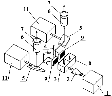
[0032] See figure 1 and figure 2 , the laser scribing equipment of this embodiment includes a laser 1, a beam expander mirror 2, a beam splitter 3, a Z-axis vibrating mirror 4, an X-axis vibrating mirror 5, a focusing mirror 6, a protective mirror 7, a Z-axis vibrating mirror 4 and a beam splitting mirror There is also a light blocking device 9 between them. A beam of laser light emitted by the laser 1 passes through the beam expander 2 and is divided into the X-axis refracted light and the Y-axis reflected light by the beam splitter 3. The refracted light passes through the Z-axis vibrating mirror 4 After polarization, it passes through the X-axis galvanometer 5, so that the laser light goes upward and then reaches the surface of the substrate film layer through the focusing lens 6 for marking, while another beam of reflected light is polarized by another Z-axis galvanometer 4 and then passes through the X-axis The vibrating mirror 5 makes the laser upward and then reaches ...

Embodiment 3

[0035] See figure 1 and Figure 4 , the laser scribing equipment of this embodiment includes a laser 1, a beam expander 2, a beam splitter 3, a Z-axis galvanometer 4, an X-axis galvanometer 5, a focusing mirror 6, a protective mirror 7 and a reflector 8, and the laser 1 emits A beam of laser light passes through the beam expander 2 and is divided into X-axis refracted light and Y-axis reflected light by the beam splitter 3. The refracted light is polarized by the Z-axis galvanometer 4 and then passes through the X-axis galvanometer 5, so that the laser goes upward and then After the focusing mirror 6 reaches the surface of the substrate film layer, it is scored, and at the same time, another beam of reflected light passes through a reflector 8 to reflect the optical path into the X axis consistent with the refracted light, and the reflected light passes through another Z axis. The mirror 4 is polarized and then passes through the X-axis vibrating mirror 5, so that the laser l...


PUM

PropertyMeasurementUnit
thicknessaaaaaaaaaa

Abstract

The invention relates to laser marking equipment for a silicon-based thin-film solar cell, and belongs to the technical field of solar cell equipment. The laser marking equipment solves the technical problem that according to existing laser marking equipment, low cost and complicated graphs cannot be achieved simultaneously. The laser marking equipment comprises an optical system and a substrate work table, wherein the optical system and the substrate work table are installed on a support. The optical system mainly comprises laser devices, beam expanders and focus lenses, wherein the output end of each laser device is provided with one beam expander. The optical system further comprises beam splitters and galvanometers, wherein the beam splitters and the galvanometers are sequentially installed between the corresponding beam expanders and the corresponding focus lenses, laser emitted by the laser devices enters the beam splitters through the beam expanders to be divided into reflective light and refracted light, the reflective light and the refracted light enter the corresponding galvanometer and the corresponding focus lens respectively to form parallel laser beams, and a film layer is marked. According to the laser marking equipment, a large-size cell with complicated graphs can be marked, the use quantity of the laser devices can be reduced, equipment cost is effectively reduced, and production efficiency is improved.

Description

technical field [0001] The invention relates to a silicon-based thin-film solar battery laser scribing equipment, which belongs to the technical field of solar battery equipment. Background technique [0002] Laser scribing equipment is an indispensable key equipment in the manufacture of silicon-based thin film solar cells. It is used to form a structure of internal multi-junction sub-cell interconnection through laser scribing on the deposited film. The principle is to use specific energy and pulse The frequency laser beam is focused on the film layer that needs to be marked, and the film layer in the radiation area is removed by using physical processes such as thermal effect and thermal stress generated by the interaction between the laser beam and the film layer. The typical manufacturing process of silicon-based thin-film solar cells requires three laser scribing processes, that is, laser scribing of the conductive film layer of the front electrode (called P1 scribing...

Claims


Application Information

Patent Timeline
Patent Type & Authority Applications(China)
IPC IPC(8): B23K26/36B23K26/04B23K26/064B23K26/142H01L31/18
CPCB23K26/04B23K26/046B23K26/064B23K26/142B23K26/361B23K26/40B23K26/702B23K2101/40B23K2103/50H01L31/18Y02P70/50
Inventor 李毅雷明初
Owner SHEN ZHEN TRONY SCI & TECH DEV CO LTD
Why Eureka
Try Eureka