Heat dissipation method and device for integrated heat pipe of large-power LED

A high-power, integrated technology, applied in lighting devices, cooling/heating devices of lighting devices, lighting and heating equipment, etc., can solve the problems of low heat transfer efficiency and large contact thermal resistance of heat pipes, and achieve simple structure and low Thermal stress, effect of improving heat dissipation performance

Active Publication Date: 2014-01-22
NANJING UNIV OF AERONAUTICS & ASTRONAUTICS
View PDF4 Cites 9 Cited by
  • Summary
  • Abstract
  • Description
  • Claims
  • Application Information

AI Technical Summary

Problems solved by technology

[0006] The purpose of the present invention is to invent a method for dissipating heat with an integrated heat pipe for high-power LEDs, and to design a method that is compatible with the heat dissipation method at the same time, aiming at the disadvantages of low heat transfer efficiency of the heat pipe and large contact thermal resistance in current high-power LED heat pipe radiators. Matching cooling device

Method used


Image

  • Heat dissipation method and device for integrated heat pipe of large-power LED
  • Heat dissipation method and device for integrated heat pipe of large-power LED
  • Heat dissipation method and device for integrated heat pipe of large-power LED

Examples


Embodiment 1

[0041] Such as figure 1 , 5 shown.

[0042] A method for dissipating heat with an integral heat pipe for high-power LEDs, comprising the following steps:

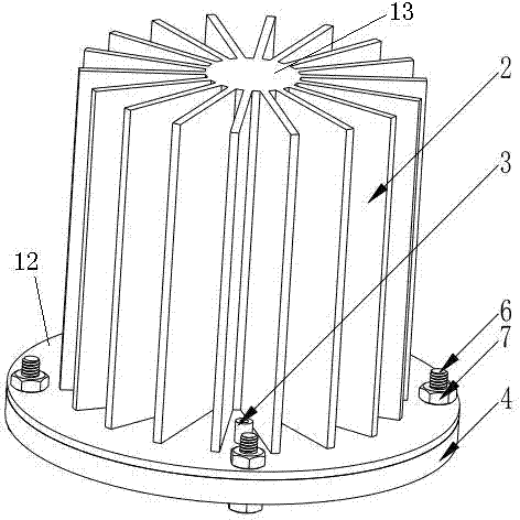
[0043] First, a plurality of cylindrical small-diameter gravity straight heat pipes are installed vertically side by side in the fixed body of the upper shell to form an array of small-diameter gravity heat pipes, and there is no communication between the vertical heat pipes; each heat pipe The wall and the fixed body of the upper casing are preferably in close contact without gaps to achieve better heat conduction. The fixed body 13 of the upper casing 12 is integrally connected with rectangular heat dissipation fins 2, wherein the gravity direct heat pipe 1, the fins 2 are made of aluminum alloy or copper material with good heat dissipation performance;

[0044] Secondly, make the evaporation ends at the lower ends of all the gravity heat pipes 1 communicate with the groove 5 on the lower cover plate 4 to form a common...

Embodiment 2

[0048] Such as Figure 1-4 shown.

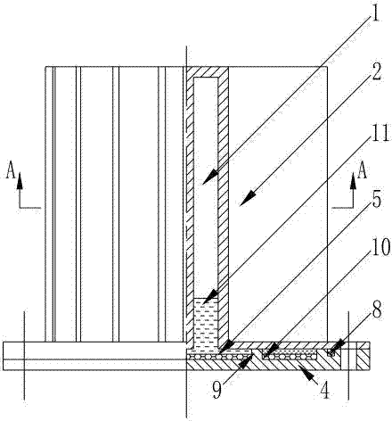
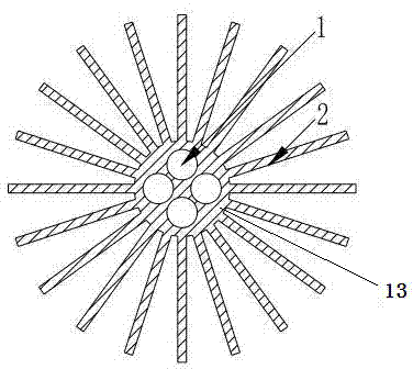
[0049] An integrated heat pipe cooling device for high-power LEDs, which includes an upper case 12 and a lower cover 4 connected to each other, the upper case 12 and the lower cover 4 are connected by bolts 6 and nuts 7, and there is an additional Equipped with rubber gasket 8 for sealing, such as figure 1 , the LED light source is mounted on the bottom surface of the lower cover plate 4, the upper surface of the lower cover plate 4 is provided with a groove 5, and a number of support columns 9 are arranged in the groove 5 ( figure 1 ) to prevent deformation due to pressure changes in the chamber, the groove 5 forms a common evaporation chamber with the lower surface of the upper shell 12 ( figure 2 ); the upper shell 12 is provided with a cylindrical fixed body 13 for fixing the gravity direct heat pipe 1, and the gravity direct heat pipe 1 is arranged around the center of the cylindrical fixed body 13, as image 3 The tube wall of each...

Embodiment 3

[0057] Such as Figure 5 , 6 .

[0058] The difference between this embodiment and embodiment 1 is that the arrangement of the gravity straight heat pipe 1 is different, Figure 5 , 6 The medium-gravity direct heat pipe 1 is fixed in the long waist-shaped fixing body 13 and is arranged in a straight line, which is suitable for narrow and long LED devices, and the rest is exactly the same as the first embodiment.


PUM


Abstract

The invention provides a heat dissipation method and device for an integrated heat pipe of a large-power LED. The method is characterized in that a plurality of cylindrical straight heat pipes are arranged side by side to form a gravity assisted heat pipe array with a small pipe diameter, vertical pipelines of all heat pipes are not communicated, meanwhile, the evaporation ends of all gravity assisted heat pipes share the same evaporator cavity, an upper shell of a heat dissipation device comprising heat pipelines and fins is manufactured in an integrated mode, a clearance between the upper shell and a cover plate forms the evaporation cavity, the upper shell and the cover plate are connected through bolts and sealed by a rubber gasket, and meanwhile the upper shell is provided with a vacuumizing and liquid injection pipe. An LED light source is attached to the heating face of the cover plate under the evaporation cavity, heat of the light source is transmitted to the fins through vapor-liquid phase-change circulation of work media in the evaporation cavity and the heat pipes, and then the heat is dissipated to the environment through the fins in a natural convection mode. The invention further provides the heat dissipation device using the heat dissipation method. The device is simple in structure, convenient to use, and good in heat dissipation effect.

Description

technical field [0001] The invention relates to an LED technology, especially a high-power LED light source heat dissipation technology, specifically a combination of high-efficiency heat transfer of heat pipes and convective heat transfer of fins, and adopts an integral manufacturing method to improve Disclosed are a heat dissipation method and a radiator for heat dissipation efficiency of a high-power LED light source. Background technique [0002] As we all know, high-power LED (Light Emitting Diode) is a high-current photoelectric device, only 15% to 25% of the electrical energy is converted into light energy during the working process, and almost all the rest of the electrical energy is converted into heat energy. If the heat generated by the LED chip cannot be dissipated in time, the junction temperature will be too high, which will affect the product life cycle, luminous efficiency, and stability. Therefore, the heat dissipation system design of high-power LED is...

Claims


Application Information

Patent Timeline
Patent Type & Authority Applications(China)
IPC IPC(8): F21V29/00F21Y101/02F21V29/51F21V29/77F21Y115/10
Inventor 周驰左敦稳孙玉利郭凌曦陈思彪
Owner NANJING UNIV OF AERONAUTICS & ASTRONAUTICS
Why Eureka
Try Eureka