Supercharge Your Innovation With Domain-Expert AI Agents!

Vapor traps for blast furnace slag handling systems

A treatment system and blast furnace slag technology, applied in the direction of recycling technology, etc., can solve the problems of difficulty in setting up the steam exhaust pipe, overflow of water vapor, and damage to the exhaust pipe, so as to achieve the effect of small installation space, reducing corrosion and solving space shortage.

Active Publication Date: 2016-01-06
北京明诚环保科技有限公司
View PDF5 Cites 0 Cited by
  • Summary
  • Abstract
  • Description
  • Claims
  • Application Information

AI Technical Summary

Problems solved by technology

Since the flushing end of the slag flushing ditch is close to the blast furnace, there are many kinds of equipment near the blast furnace, and the space is tight, so it is difficult to install the exhaust cylinder at the flushing end of the slag flushing ditch
Therefore, some methods are to increase the height of the exhaust cylinder in order to increase the exhaust steam volume of the exhaust cylinder, but when the height of the exhaust cylinder is too high, it will cause an increase in cost, and when the wind is strong, the exhaust cylinder will produce lateral wind vibration , when the wind vibration frequency is close to the natural frequency, resonance occurs, causing the exhaust tube to be damaged or blown down
Moreover, even if the height of the exhaust cylinder is increased, a large amount of water vapor still overflows from the flushing end of the slag flushing ditch

Method used


Image

  • Vapor traps for blast furnace slag handling systems
  • Vapor traps for blast furnace slag handling systems
  • Vapor traps for blast furnace slag handling systems

Examples


Embodiment Construction

[0046] The present invention will be described in further detail below in conjunction with the accompanying drawings and specific embodiments, but not as a limitation of the present invention.

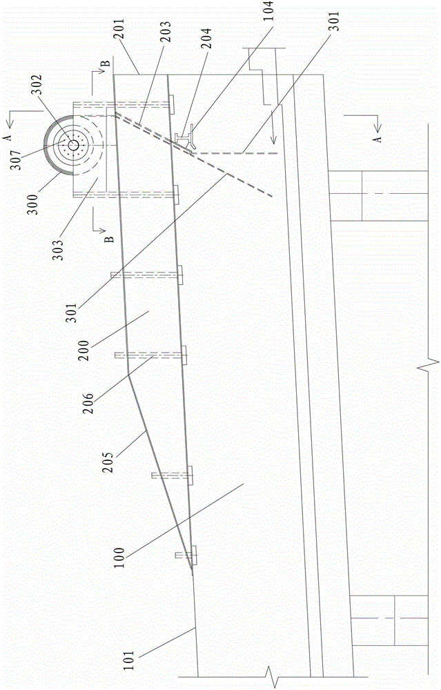
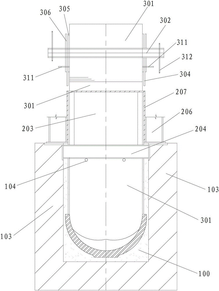
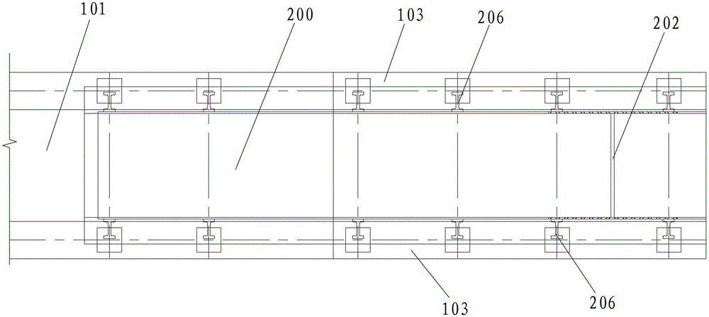
[0047] Such as figure 1 , figure 2 and image 3 As shown, the vapor barrier device used in the blast furnace slag treatment system of the present invention is arranged on the flushing end of the slag flushing ditch 100 , and a cover plate 101 is arranged on the slag flushing ditch 100 . The steam trap for the blast furnace slag treatment system includes: a steam trap 200 and a shaft device 300 , the vapor trap 200 is set on the flushing end of the slag flushing ditch 100 . One end of the vapor trap 200 is connected to the cover plate 101 of the slag flushing ditch 100 , and the other end of the vapor trap 200 is provided with a blocking plate 201 for closing the other end of the vapor trap 200 . The drum shaft device 300 is erected above the steam trap 200 , and the drum shaft devi...


PUM

PropertyMeasurementUnit
thicknessaaaaaaaaaa

Abstract

The invention discloses a vapor-proof device for a blast furnace slag treating system. The vapor-proof device comprises a vapor-proof cover and a barrel shaft device, wherein the vapor-proof cover is covered on a slag sluice, one end of the vapor-proof cover is connected with a cover plate of the slag sluice, and the other end of the vapor-proof cover is provided with a blocking plate for sealing the other end of the vapor-proof cover; the barrel shaft device is erected above the vapor-proof cover, and a vapor-proof curtain matched with the slag sluice in width is wound on the barrel shaft device; the vapor-proof cover is provided with a long and narrow slit for allowing the vapor-proof curtain to pass through and blocking the crushing end of the slag sluice, and the length direction of the long and narrow slit is consistent with the width direction of the slag sluice. The vapor-proof device is simple in structure, small in occupied space for installation and convenient to operate; meanwhile, a dredging and blocking combination method is adopted in the invention, so that vapor is effectively prevented from overflowing at the crushing end of the slag sluice and can be discharged from the tail of the slag sluice, the problem of the insufficient area in front of a furnace is solved, and the environment pollution is also avoided.

Description

technical field [0001] The invention relates to a steam isolation device, and its characteristics relate to a steam isolation device used in a blast furnace slag treatment system. Background technique [0002] Blast furnace smelting is one of the most important methods of iron production. The main product of blast furnace smelting is pig iron, and the by-products are slag, gas and furnace dust. With the development of large-scale blast furnaces and the improvement of the effective volume utilization coefficient of blast furnaces, the blast furnace slag treatment system becomes more and more important along with the blast furnace production, and higher requirements are put forward for the blast furnace slag treatment capacity. Blast furnace slag has many uses. The high-temperature liquid slag is rapidly cooled with water to make water slag, which is the first-class raw material for making bricks and cement. The water quenching process of blast furnace slag is currently the m...

Claims


Application Information

Patent Timeline
Patent Type & Authority Patents(China)
IPC IPC(8): C21B3/06
CPCY02W30/50
Inventor 魏彦杰
Owner 北京明诚环保科技有限公司
Features
  • R&D
  • Intellectual Property
  • Life Sciences
  • Materials
  • Tech Scout
  • Unparalleled Data Quality
  • Higher Quality Content
  • 60% Fewer Hallucinations
Learn More