Unconventional gas liquefaction system based on spiral wound heat exchanger

A winding tube heat exchanger technology, applied in the field of unconventional natural gas liquefaction system, can solve the problems of large changes in raw gas components, high energy consumption, poor heat transfer performance, etc., and it is difficult to achieve the flow channel and high efficiency , the effect of large operating flexibility

Active Publication Date: 2014-01-29
CHINA NAT OFFSHORE OIL CORP +1
View PDF10 Cites 7 Cited by
  • Summary
  • Abstract
  • Description
  • Claims
  • Application Information

AI Technical Summary

Problems solved by technology

With the rapid development of unconventional natural gas such as coal-to-gas and coke oven tail gas, the existing domestic mixed refrigerant cycle refrigeration technology is applied to raw gas components with large changes and high impurities such as nitrogen, hydrogen, and heavy hydrocarbons. Unconventional natural gas will cause problems such as poor heat transfer performance and high energy consumption

Method used


Image

  • Unconventional gas liquefaction system based on spiral wound heat exchanger

Examples


Embodiment Construction

[0019] The invention will be further described below in conjunction with the accompanying drawings, but the invention is not limited to the following embodiments.

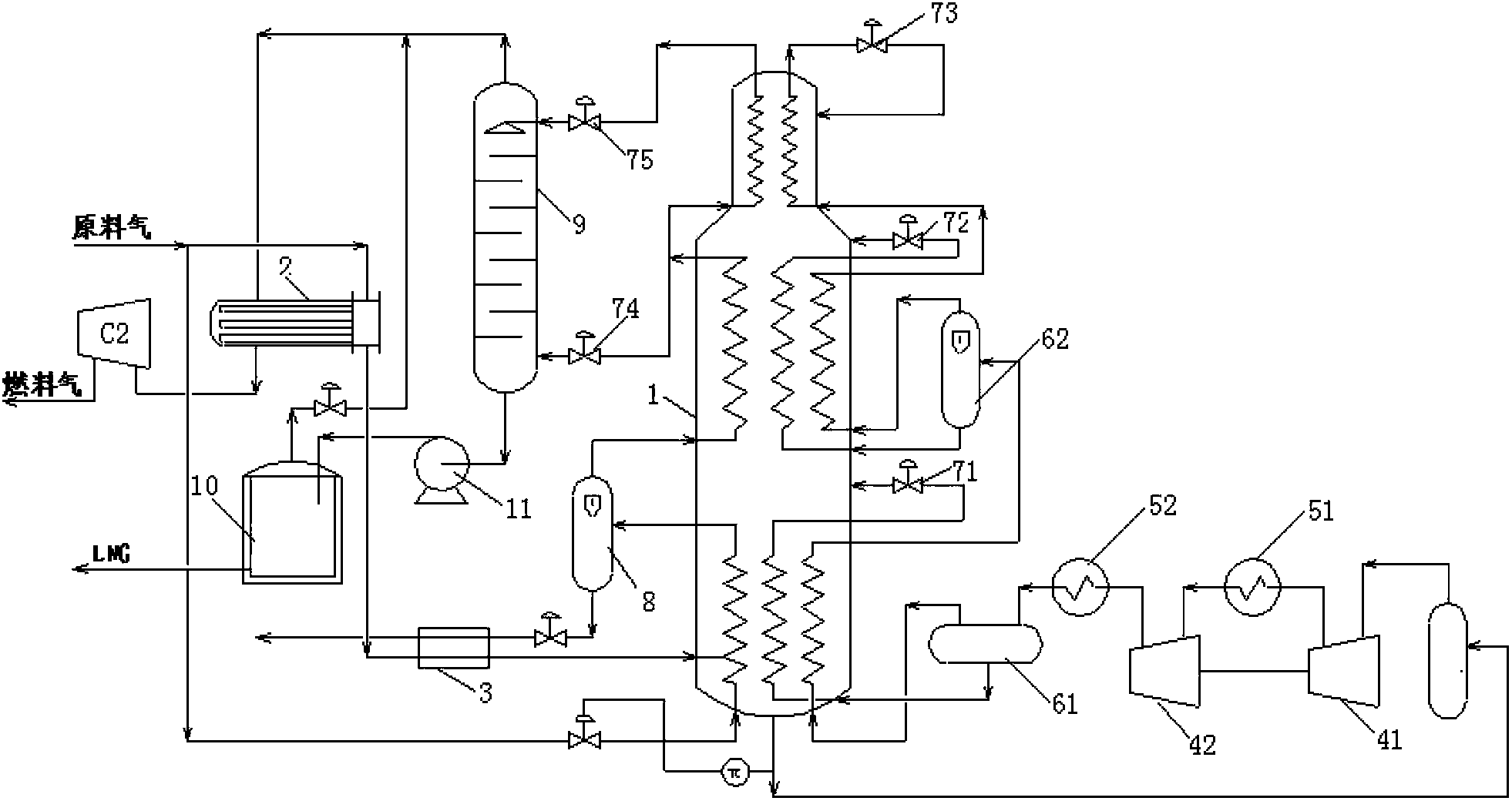
[0020] Such as figure 1 As shown, the unconventional natural gas liquefaction system based on the coiled tube heat exchanger provided by the present invention includes a coiled tube heat exchanger 1, a fuel gas heat exchanger 2, a heavy hydrocarbon heat exchanger 3 and a mixed refrigerant circulation mechanism; The mixed refrigerant circulation mechanism includes a first-stage mixed refrigerant compressor 41, a first-stage mixed refrigerant compressor cooler 51, a second-stage mixed refrigerant compressor 42, and a second-stage mixed refrigerant compressor cooler 52 connected in sequence. Both the first-stage mixed refrigerant compressor 41 and the second-stage mixed refrigerant compressor 42 are centrifugal compressors; the outlet of the second-stage mixed refrigerant compressor cooler 52 communicates with a mixed...


PUM


Abstract

The invention discloses an unconventional gas liquefaction system based on a spiral wound heat exchanger. The liquefaction system comprises the spiral wound heat exchanger, a fuel gas heat exchanger, a heavy hydrocarbon heat exchanger and a mixed refrigerant circulation mechanism. The mixed refrigerant circulation mechanism comprises a primary mixed refrigerant compressor and a primary mixed refrigerant compressor cooler, wherein the primary mixed refrigerant compressor and the primary mixed refrigerant compressor cooler are sequentially connected. The fuel gas heat exchanger, the heavy hydrocarbon heat exchanger and a pre-cooling section of the spiral wound heat exchanger are sequentially communicated with one another, and an outlet of the pre-cooling section of the spiral wound heat exchanger is communicated with the heavy hydrocarbon heat exchanger. A qualified component outlet of the heavy hydrocarbon heat exchanger is communicated with a liquefaction section of the spiral wound heat exchanger, an outlet of the liquefaction section of the spiral wound heat exchanger is communicated with a low-temperature rectifying tower and a super-cooling section of the spiral wound heat exchanger, an outlet of the super-cooling section of the spiral wound heat exchanger is communicated with the low-temperature rectifying tower, and the bottom portion of the low-temperature rectifying tower is communicated with an LNG storage tank. The spiral wound heat exchanger is adopted as a main heat exchanger and has the advantages of being firm in structure, allowing a runner not to be easily blocked, being less in leakage point and allowing large-temperature-difference heat transmission in comparison with a louvered fin heat exchanger.

Description

technical field [0001] The invention relates to an unconventional natural gas liquefaction system based on a coiled tube heat exchanger, and belongs to the technical field of unconventional natural gas liquefaction such as coal gas and coke oven tail gas. Background technique [0002] At present, the common mixed refrigerant circulation refrigeration process in China is mostly based on plate-fin heat exchangers, which are well applied in liquefaction plants that use conventional natural gas as raw material gas. With the rapid development of unconventional natural gas such as coal-to-gas and coke oven tail gas, the existing domestic mixed refrigerant cycle refrigeration technology is applied to raw gas components with large changes and high impurities such as nitrogen, hydrogen, and heavy hydrocarbons. When unconventional natural gas is used, it will bring problems such as poor heat transfer performance and high energy consumption. [0003] Internationally, the coiled tube h...

Claims


Application Information

Patent Timeline
Patent Type & Authority Applications(China)
IPC IPC(8): F25J1/02F25J5/00C10L3/10
CPCF25J1/0022F25J1/004F25J1/0045F25J1/0055F25J1/0212F25J1/0264F25J2210/06F25J2220/62F25J2220/64F25J2245/90
Inventor 唐令力单彤文陈杰花亦怀浦晖邰晓亮冯颉
Owner CHINA NAT OFFSHORE OIL CORP
Why Eureka
Try Eureka