
Resin molding machine and method of resin molding

A resin mold and resin technology, applied in the manufacture of electrical components, electrical solid devices, semiconductor/solid devices, etc., can solve the problems of difficult demoulding, unstable position accuracy of movable pins, and easy wrinkles, etc., to improve filling and The effect of forming quality

Active Publication Date: 2014-01-29
APIC YAMADA CORP
View PDF5 Cites 19 Cited by
  • Summary
  • Abstract
  • Description
  • Claims
  • Application Information

AI Technical Summary

Problems solved by technology

At this time, the release film is supported in a discontinuous state between the inner-diameter-side lens recess and the outer-diameter-side lens recess of the cavity unit, and even if the molding resin is filled in this state, air is easily entrapped in the discontinuous surface. , and when the movable unit is raised, wrinkles are likely to occur due to the relaxation of the release film, so the molding quality of the lens part is likely to be reduced
In addition, when the number of lens parts increases, the positional accuracy of a plurality of movable pins may become unstable.
[0016] In addition, when using transfer molding to perform resin molding of, for example, LEDs with lenses, the transparent resins (silicon-based resins, epoxy-based resins, urethane-based resins, acrylic resins, etc.) The mold temperature after molding makes the surface of the molded product in a state of incomplete curing and stickiness (tackiness), and the curing cannot be accelerated unless the surface temperature of the molded product drops to close to normal temperature
In transfer molding, the mold is opened to take out the molded product in a state heated to the molding temperature, and the demoulding in the heated state is the clamping surface of the mold and the release film, and the release film and the molded product respectively. Pasted state, difficult to demould
[0017] In addition, there is also a method of releasing the mold using a push pin, but in the case of an elastic system molding resin with elasticity, the release effect is insufficient, and only the periphery of the push pin may be broken.
In particular, for LEDs with lenses, if physical damage such as dents remains on the resin surface, it is likely to become a defective product

Method used


Image

  • Resin molding machine and method of resin molding
  • Resin molding machine and method of resin molding
  • Resin molding machine and method of resin molding

Examples


no. 2 Embodiment

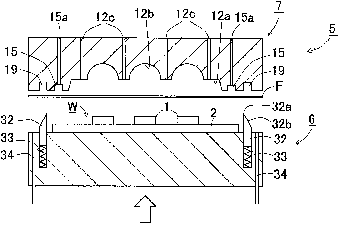
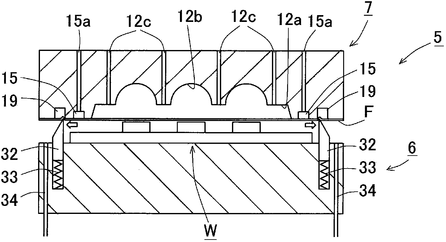
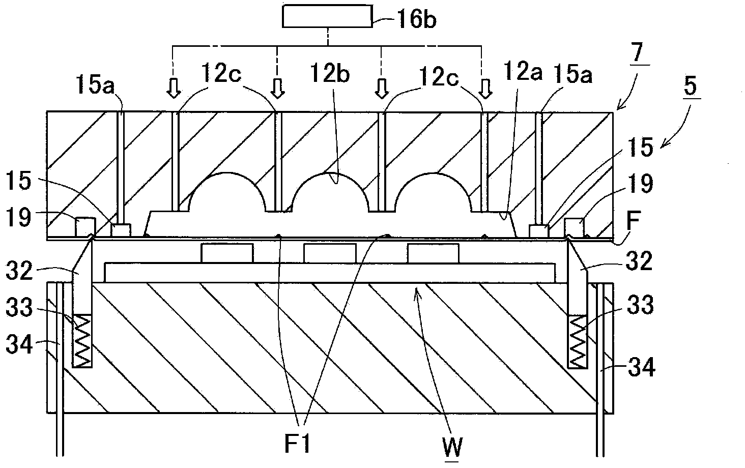
[0116] The case where the release film is sucked in the cavity, the resin molding apparatus, and the resin molding method will be described in detail. The same reference numerals are assigned to the same components as those in the first embodiment, and the above descriptions are referred to. exist Figure 12 Among them, the molding die 5 and the pressure driving mechanism are the same as those of the first embodiment. Also in this embodiment, the upper die 7 will be described as a fixed die and the lower die 6 will be described as a movable die. A first cavity concave portion 12 a is formed on an upper die clamping surface of a cavity core (cavity insert) 11 provided on the upper die 7 .

[0117] The first cavity recessed portion 12 a is used to house and mold the workpiece W on which the light emitting elements 1 are mounted in a matrix on the substrate 2 as a whole. In addition, a plurality of second cavity recesses 12b having a depth deeper than the depth of the cavity b...

no. 3 Embodiment

[0143] The resin molding apparatus and method for blowing and releasing the mold after forming will be described in detail. The same reference numerals are assigned to the same components as those in the first embodiment, and the above descriptions are referred to.

[0144] exist Figure 11 In the work W, light-emitting elements 1 are flip-chip-connected (or wire-bonded) on a substrate 2 in a row-column manner. exist Figure 9 In the case of a rectangular (short length) substrate 2 , an example in which a plurality of (for example, 18) molded products are mounted is shown in . In addition, various plate-shaped members such as a resin substrate, a metal (for example, aluminum, copper, etc.) substrate, a ceramic substrate, a lead frame, and a carrier can be used as the substrate 2 used as a base material. In addition, as the workpiece W, a wafer on which bumps are formed, a carrier on which electronic components are mounted and fixed by bonding, or the like can be used.

[0...

no. 4 Embodiment

[0168] The resin molding apparatus and method of the molded film supporting pin and air blowing combined type will be described in detail. The same reference numerals are assigned to the same components as those in the first embodiment, and the above descriptions are referred to. exist Figure 32 Herein, the schematic structure and the pressure driving mechanism of the molding die 5 are the same as those of the first to third embodiments, and the description will focus on different structures. It should be noted that because the release using the membrane support pin is to be explained in detail, the Figure 32 to Figure 36 Illustration of the peripheral groove 15 , the film wrinkle correcting member 32 for flattening the wrinkle of the release film, the housing recess 19 , and the air blowing units 27 , 28 , which are necessary structures before forming, is omitted.

[0169] First, refer to Figure 8 The structure of the upper die 7 will be described. A peripheral groove ...


PUM


Abstract

The resin-molding apparatus improving further more, the filling ability and molding quality of the epoxy molded compound the work is resin-molded using the release film and resin-molding method of the long person shape are provided. The possible to squirt air and alienate the release film (F) from the molding clamp plane multiple vent holes (12c, 12e, 18a, 18b) inhaling air and absorbs the release film (F) in the avoirdupois clamp side or are installed in the avoirdupois (7). And in the type (6), as long as the width direction both sides of the release film (F) of the long person shape which is faced with the work mounting side and is returned suffers in the width direction both sides of the release film (F) of the long person shape and it is pressed down with the release film (F) and the tension is applied to not only the longitudinal direction but also the width direction and the film wrinkle is removed the film wrinkle correcting member (32) of pair is installed.

Description

technical field [0001] The present invention relates to a resin molding device and a resin molding method for resin molding a workpiece using a release film. Background technique [0002] In the past, in order to reduce mold maintenance and improve productivity and molding quality, resin molding equipment that covers the mold clamping surface of the mold with a release film (Japanese: リリースfilm) and performs resin molding has been put into practical use. For example, a film processor is attached to a molding die or a resin molding device, and a long release film is wound up on a winding reel via a die surface from a supply roll. [0003] As an example, there has been proposed a resin molding apparatus for resin-molding a workpiece on which a light emitting element is mounted on a substrate using a release film. Use transparent resin with high adhesiveness (silicon-based resin, epoxy-based resin, urethane-based resin, acrylic resin, etc.) Deep) moldings are resin molded. Sp...

Claims


Application Information

Patent Timeline
IPC IPC(8): H01L21/56
CPCB29C45/26B29C2045/14155H01L21/561H01L21/565H01L21/566H01L24/97H01L2924/1461H01L2924/15787H01L2924/181H01L2924/1815H01L2924/00H01L33/00
Inventor 齐藤高志
Owner APIC YAMADA CORP
Learn More