
High-linearity relaxation oscillator

A relaxation oscillator and high linearity technology, applied in the direction of electric pulse generator circuit, differential amplifier to generate pulses, etc., can solve the problems of reducing frequency-controlling current linearity, limiting the maximum frequency range of the oscillator, etc., to improve linearity Effect

Active Publication Date: 2014-01-29
SOUTHEAST UNIV
View PDF3 Cites 46 Cited by
  • Summary
  • Abstract
  • Description
  • Claims
  • Application Information

AI Technical Summary

Problems solved by technology

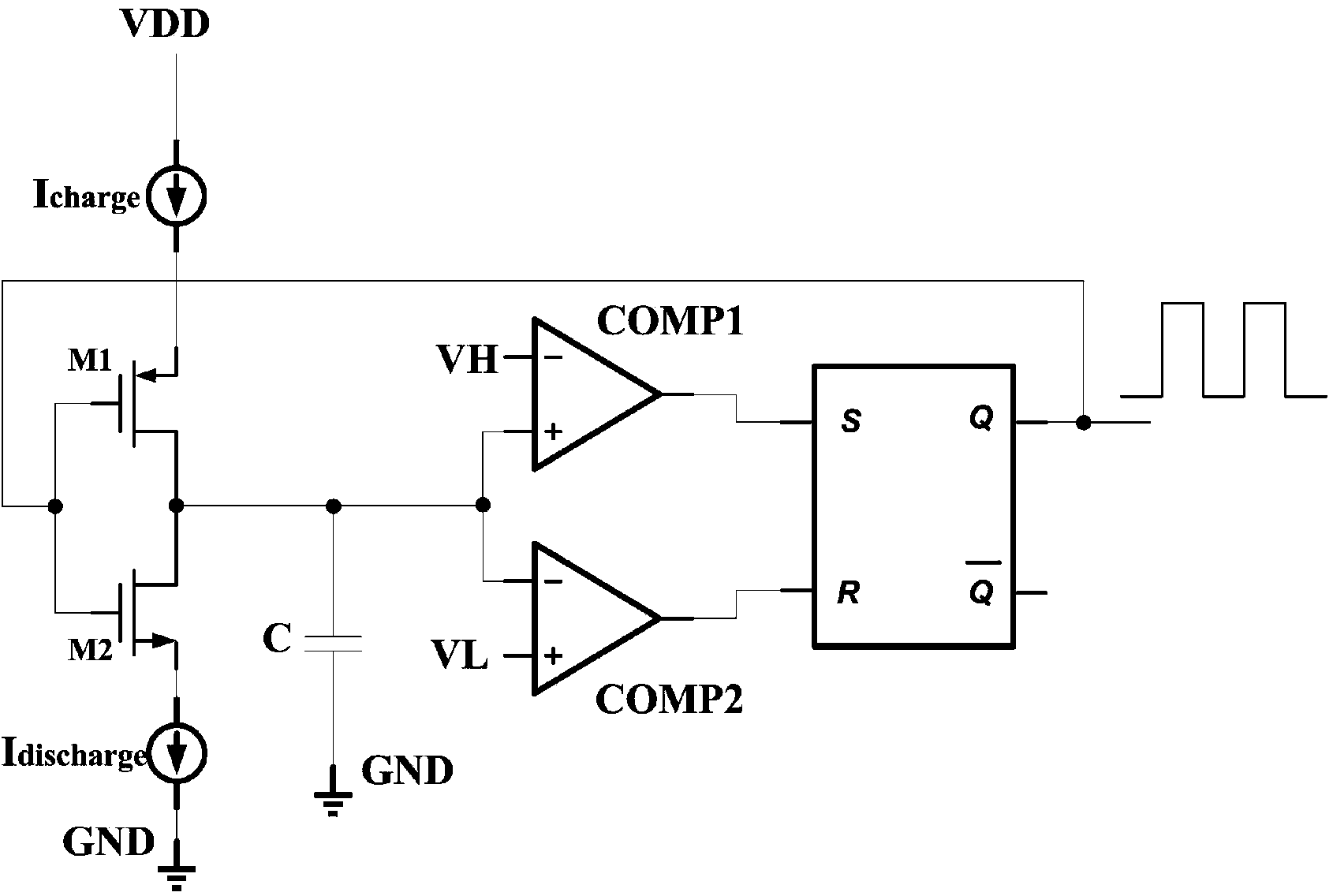
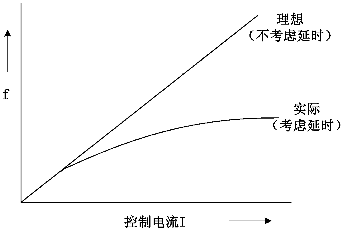
[0028] Although, a current-controlled relaxation oscillator with dual timing capacitors will delay by 4t in one cycle d reduced to 2t d , but the output frequency of the oscillator is still subject to the control circuit of the oscillation amplitude of the timing capacitor and the delay 2t of the PMOS transistor M1, NMOS transistor M2, PMOS transistor M3, and NMOS transistor M4 as control switches d effect, especially at high frequencies, the 2t d The delay is even greater than the period of the oscillator output waveform, which not only reduces the linearity of the frequency-controlled current, but also limits the maximum frequency range of the oscillator. Therefore, it is necessary to further improve the current-controlled relaxation oscillator with dual timing capacitors. , to reduce the effect of delay

Method used


Image

  • High-linearity relaxation oscillator
  • High-linearity relaxation oscillator
  • High-linearity relaxation oscillator

Examples


Embodiment Construction

[0058] refer to Figure 6 The relaxation oscillator with high linearity of the present invention includes an oscillation circuit 1, a reference level self-adjustment circuit 2, and a transmission gate selection signal generation circuit 3, wherein the non-ground terminal output of the capacitor C1 in the oscillation circuit 1 is connected to the reference level self-adjustment The input of the circuit 2, the output of the reference level self-adjusting circuit 2 are connected to the inverting terminals of the first comparator COMP1 and the second comparator COMP2 in the oscillation circuit 1, and the output V of the transmission gate selection signal generation circuit 3 φ Connected to the gate terminal of the PMOS of the first transmission gate TG1 in the reference level self-adjusting circuit 2 and the gate terminal of the NMOS of the second transmission gate TG2, the output of the transmission gate selection signal generation circuit 3 It is connected to the NMOS gate term...


PUM


Abstract

The invention provides a relaxation oscillator of which the linearity is significantly improved. The relaxation oscillator comprises an oscillating circuit, a reference level self-regulating circuit and a transmission gate selective signal generating circuit. Capacitor voltage overshoot caused by delay of a control circuit is worked out by detecting the voltage peak of charge and discharge capacitors in the oscillating circuit, and accordingly the reference level of comparators in the oscillating circuit is reduced by a corresponding quantity to serve as a new reference level so that the oscillation amplitude of the charge and discharge capacitors can be just a theoretical value. According to the high-linearity relaxation oscillator, when the new reference level is larger than zero, influence, brought by the capacitor voltage overshoot caused by delay of the control circuit, of the charge and discharge capacitors on output frequency is eliminated, and the linearity of a frequency-control circuit of the relaxation oscillator is significantly improved. The transmission gate selective signal generating circuit provides the initial reference level for the comparators by controlling transmission gates and transmits the new reference level to the reverse phase ends of the comparators when the new reference level is generated, and therefore the initial reference level can be isolated from the reverse phase ends of the comparators.

Description

technical field [0001] The invention relates to the field of CMOS integrated circuits, in particular to a relaxation oscillator with high linearity, which remarkably improves the frequency-control current linearity through self-regulation of a comparator reference level. Background technique [0002] In large-scale integrated circuits, clock signals are generally generated by oscillators. The relaxation oscillator has a simple structure, low cost, easy integration, and relatively low power consumption. It is the most widely used clock generation circuit in the oscillator. [0003] In the application of signal modulation and demodulation, data recovery of storage system, etc., it is required that the frequency-control current of the relaxation oscillator used has a high linearity, so as to reduce distortion and increase the relaxation oscillation frequency range of the device. In relaxation oscillators, the frequency-control current linearity is related to the delay of the ...

Claims


Application Information

Patent Timeline
IPC IPC(8): H03K3/023
Inventor 孙伟锋张允武林吉勇祝靖钱钦松陆生礼时龙兴
Owner SOUTHEAST UNIV
Learn More